BCD-to-7-Segment Decoder
Overview
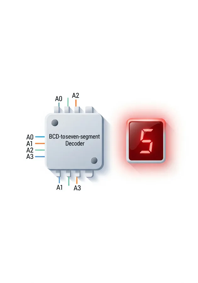
- Purpose: The BCD-to-7-Segment Decoder is a combinational circuit that converts a 4-bit Binary Coded Decimal (BCD) value (0–9) into the seven control signals (a–g) needed to display that digit on a seven-segment display.
- Symbol: A decoder block with four inputs on the left (A0–A3) and seven outputs on the right (a–g). In DigiSim.io it is labelled BCD / 7-SEG.
- DigiSim.io Role: It is the bridge between counting/arithmetic logic (which works in binary) and a human-readable numeric display. It mirrors classic decoder ICs such as the 7447/7448.
Functional Description
Logic Behavior
The decoder reads the 4-bit BCD value on A0–A3 (A0 is the least-significant bit) and drives the seven segment outputs a–g with the active-high pattern for that digit. Inputs 1010–1111 (10–15) are non-decimal and blank the display (all segments off), the same convention used by the 7448.
Truth Table (segment = 1 means lit):
| Digit | A3 A2 A1 A0 | a | b | c | d | e | f | g |
|---|---|---|---|---|---|---|---|---|
| 0 | 0000 | 1 | 1 | 1 | 1 | 1 | 1 | 0 |
| 1 | 0001 | 0 | 1 | 1 | 0 | 0 | 0 | 0 |
| 2 | 0010 | 1 | 1 | 0 | 1 | 1 | 0 | 1 |
| 3 | 0011 | 1 | 1 | 1 | 1 | 0 | 0 | 1 |
| 4 | 0100 | 0 | 1 | 1 | 0 | 0 | 1 | 1 |
| 5 | 0101 | 1 | 0 | 1 | 1 | 0 | 1 | 1 |
| 6 | 0110 | 1 | 0 | 1 | 1 | 1 | 1 | 1 |
| 7 | 0111 | 1 | 1 | 1 | 0 | 0 | 0 | 0 |
| 8 | 1000 | 1 | 1 | 1 | 1 | 1 | 1 | 1 |
| 9 | 1001 | 1 | 1 | 1 | 1 | 0 | 1 | 1 |
Inputs and Outputs
- Inputs:
A0,A1,A2,A3— the 4-bit BCD value (A0 = LSB). - Outputs:
a,b,c,d,e,f,g— the seven segment drives, active-high. Wire each one to the matching segment input of a 7-Segment Display.
Configurable Parameters
None. The mapping is fixed (standard decimal font); behaviour depends only on the BCD value present at the inputs.
Visual Representation in DigiSim.io
The component renders as a decoder body with the inputs A0–A3 stacked on the left and the seven segment outputs a–g on the right. Drive the inputs from switches, a counter, or any 4-bit logic, and connect the outputs to a Seven-Segment Display to see the digit appear.
Educational Value
Key Concepts
- BCD encoding — representing each decimal digit 0–9 as a 4-bit binary value.
- Combinational decoding — turning a coded input into a fixed output pattern, with no memory or clock.
- Display driving — separating the value (binary) from its presentation (lit segments).
Learning Objectives
- Read a seven-segment truth table and relate each digit to its lit segments.
- Connect a binary counter to a decoder and display to build a counting digit.
- Understand why values above 9 are blanked in a BCD decoder.
Usage Examples/Scenarios
- Single counting digit: a 4-bit counter → BCD-to-7-segment decoder → seven-segment display shows 0–9.
- Multi-digit clock or counter: one decoder + display per digit, fed by cascaded mod-10 / mod-6 counters (see the Digital Clock demo).
- Manual experiment: four switches set a BCD value and the display shows the corresponding digit.
Applications
- Digital clocks, timers, and stopwatches.
- Counters, scoreboards, and tally displays.
- Voltmeters, thermometers, and other numeric instrument read-outs.
- Any project that turns a binary number into a visible decimal digit.
Limitations
- Decodes a single decimal digit (0–9); multi-digit numbers need one decoder + display per digit.
- Inputs 10–15 blank the display rather than showing hexadecimal letters. For hex (0–F) use the Digit Display component instead.
- Purely combinational — it holds no value; latch or count upstream if you need the digit to persist.
Related Components
- 7-Segment Display — the output device this decoder drives.
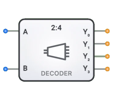
- Decoder (3-to-8) / Decoder (2-to-4) — one-hot address decoders; related decoding logic.
- Digit Display — a built-in hex (0–F) display that needs no external decoder.
- Counter — the usual source of the BCD value feeding this decoder.