XOR 게이트
개요
- 목적: XOR (배타적 OR) 게이트는 홀수 개의 입력이 HIGH일 때 HIGH (논리 '1')를 출력하는 논리 연산을 수행합니다. 2입력 XOR 게이트의 경우 정확히 하나의 입력이 HIGH일 때 출력이 HIGH입니다.
- 기호: XOR 게이트는 입력 측에 이중 곡선이 있는 기호로 표현되며, 일반 OR 게이트와 구별됩니다.
- DigiSim.io 역할: 산술 회로, 비교기 및 오류 검출 시스템을 구축하기 위한 기본 컴포넌트 역할을 합니다.
기능 설명
논리 동작
XOR 게이트는 배타적 논리합을 구현하며, 홀수 개의 입력이 HIGH일 때 HIGH 출력을 생성합니다.
진리표 (2입력 XOR 게이트):
| Input A | Input B | Output Y |
|---|---|---|
| 0 | 0 | 0 |
| 0 | 1 | 1 |
| 1 | 0 | 1 |
| 1 | 1 | 0 |
부울 표현식: Y = A ⊕ B (Y는 A XOR B)
입력 및 출력
- 입력: XOR 게이트는 2개의 입력(A, B)을 가집니다.
- 출력: XOR 연산 결과를 나타내는 단일 1비트 출력입니다.
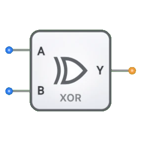
DigiSim.io에서의 시각적 표현
XOR 게이트는 왼쪽에 입력 핀, 오른쪽에 출력 핀이 표시됩니다. 기호에는 OR 게이트와 구별되는 특징적인 입력 측 이중 곡선이 포함됩니다. 회로에 연결되면 컴포넌트는 연결 와이어의 색상 변화를 통해 핀의 논리 상태를 시각적으로 나타냅니다.
교육적 가치
핵심 개념
- 부울 대수: 배타적 OR 연산을 별도의 부울 함수로 보여줍니다.
- 조합 논리: 게이트의 출력이 현재 입력 값에 의해서만 결정되는 방법을 보여줍니다.
- 비트 비교: 비트가 다를 때를 감지하는 개념을 설명합니다.
- 산술 연산: 이진 덧셈 회로에서 XOR이 사용되는 방법을 소개합니다.
학습 목표
- 배타적 OR 연산과 진리표 표현을 이해합니다.
- 포함적 OR (OR 게이트)와 배타적 OR (XOR 게이트)의 차이를 배웁니다.
- XOR 게이트가 산술 회로, 특히 이진 덧셈에서 사용되는 방법을 인식합니다.
- 오류 검출 시스템을 위한 패리티 생성/검사에 XOR 게이트를 적용합니다.
사용 예시/시나리오
- 이진 덧셈: 반가산기 회로에서 XOR 게이트는 두 이진 입력의 합 비트를 생성합니다.
- 패리티 생성/검사: 오류 검출을 위한 데이터 전송에서 패리티 비트를 생성하거나 검증합니다.
- 비트 비교기: 두 이진수에서 대응하는 비트가 다를 때를 감지합니다.
- 제어된 인버터: 하나의 제어 입력이 있는 XOR 게이트를 사용하여 신호를 선택적으로 반전시킵니다.
기술 참고사항
- 입력 중 하나라도 하이 임피던스(high-Z) 상태이거나 정의되지 않은 경우 XOR 게이트의 출력은 하이 임피던스(high-Z)를 나타냅니다.
- DigiSim.io에서는 기본 논리 게이트이지만, XOR 게이트는 물리적 회로에서 AND, OR, NOT 게이트의 조합을 사용하여 구현됩니다.
- 다입력 XOR 게이트의 경우 홀수 개의 입력이 HIGH일 때만 출력이 HIGH이므로 패리티 계산에 유용합니다.
트랜지스터 레벨 구현
- CMOS: 상보적 MOSFET 쌍 사용
- TTL: 바이폴라 접합 트랜지스터 사용
집적 회로
- 74xx86: 쿼드 2입력 XOR 게이트
- 74xx266: 쿼드 2입력 XNOR 게이트
전송 게이트 구현
- 상보적 패스 트랜지스터 사용
- 특정 응용에 효율적
회로 구현 (기본 게이트를 사용한 2입력 XOR)
graph LR
    A[Input A] --> NOT1[NOT Gate]
    B[Input B] --> NOT2[NOT Gate]

    NOT1 --> AND1[AND Gate]
    B --> AND1

    A --> AND2[AND Gate]
    NOT2 --> AND2

    AND1 --> OR[OR Gate]
    AND2 --> OR
    OR --> Y[Output Y]
논리: Y = A·B̄ + Ā·B (A XOR B는 입력이 다를 때 HIGH를 생성)
부울 방정식
2입력 XOR 게이트:
- Y = A ⊕ B
- Y = A·B̄ + Ā·B
- Y = (A + B) · (Ā + B̄)
- Y = A ≠ B (부등식)
3입력 XOR 게이트:
- Y = A ⊕ B ⊕ C
- Y = A·B̄·C̄ + Ā·B·C̄ + Ā·B̄·C + A·B·C
관련 컴포넌트
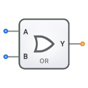
- OR 게이트: 입력 중 하나라도 참이면 참을 출력합니다
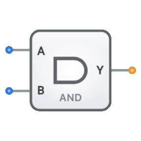
- AND 게이트: 모든 입력이 참일 때만 참을 출력합니다
- XNOR 게이트: XOR의 보수로, 입력이 같을 때 참을 출력합니다
- 반가산기: 이진 덧셈을 위해 XOR 및 AND 게이트를 결합합니다
- 전가산기: 합 생성에 XOR 게이트를 사용합니다
- 패리티 생성기/검사기: 오류 검출에 XOR 게이트를 사용합니다
- 멀티플렉서: 적절한 구성으로 XOR 기능을 구현할 수 있습니다
- 제어된 인버터: 특정 응용에서 유사한 기능을 합니다