어셈블리 프로그램 로더
개요
- 목적: 어셈블리 프로그램 로더는 어셈블리 언어 프로그램을 이진 기계 코드로 변환하고 메모리 구성 요소에 로드하는 특수 구성 요소입니다. 사람이 읽을 수 있는 어셈블리 코드와 디지털 회로가 처리할 수 있는 이진 명령 사이의 격차를 메웁니다.
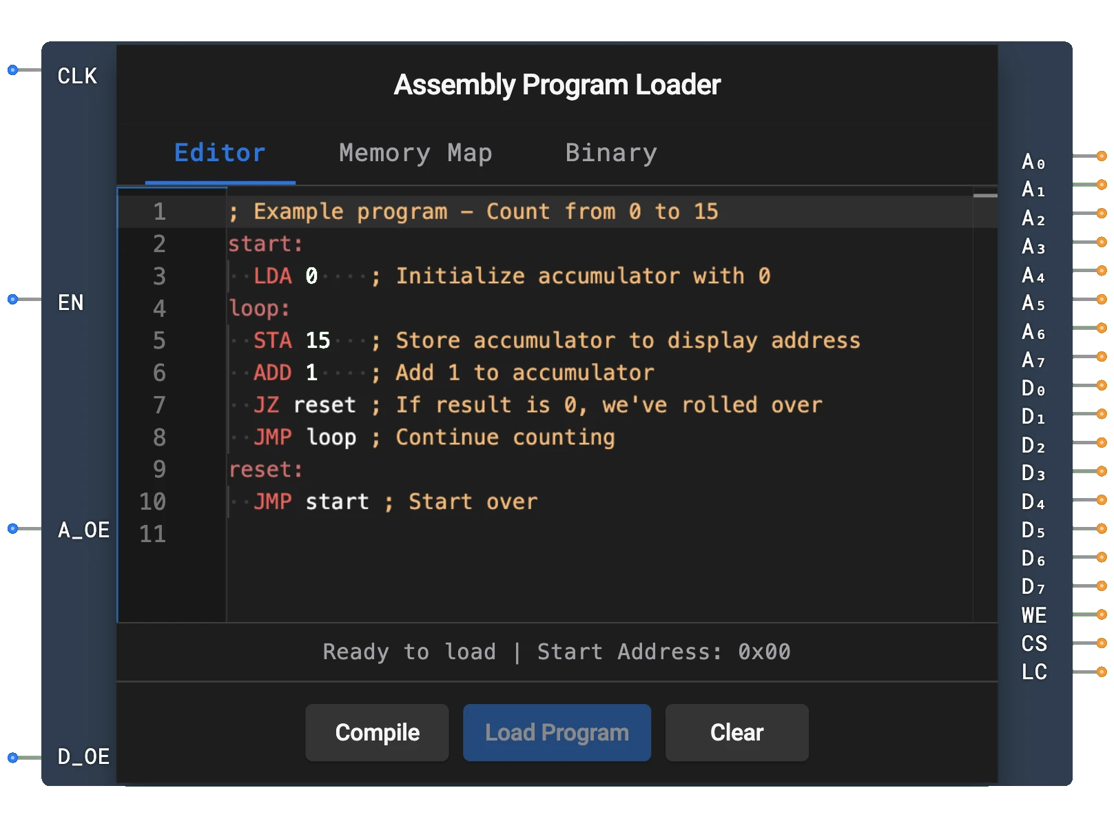
- 기호: 어셈블리 프로그램 로더는 클록, 인에이블, 주소 출력 인에이블, 데이터 출력 인에이블에 대한 입력과 주소 버스, 데이터 버스, 쓰기 인에이블, 칩 선택, 로드 완료에 대한 출력이 있는 직사각형 블록으로 표현됩니다.
- DigiSim.io 역할: 코드를 수동으로 이진으로 변환하지 않고도 CPU 설계에서 어셈블리 프로그램을 테스트하고 실행할 수 있게 하여 컴퓨터 아키텍처 개념을 탐구하는 필수 교육 도구입니다.
기능 설명
논리 동작
어셈블리 프로그램 로더는 사용자가 입력한 어셈블리 코드를 읽어 기계 코드로 변환하고 순차적으로 메모리 주소에 씁니다. 유휴, 로딩, 완료의 별개 단계가 있는 상태 기계로 동작합니다.
운영 흐름:
- 로더가 트리거될 때(속성 대화상자를 통해) 변환 프로세스를 시작합니다
- EN이 HIGH인 동안 각 상승 CLK 에지에서 로더는 다음 명령으로 진행합니다
- 로딩 중 WE 및 CS 출력이 HIGH입니다
- 로딩이 완료되면 LC(로드 완료) 출력이 HIGH가 됩니다
- A_OE가 HIGH일 때 주소 출력이 구동되고; D_OE가 HIGH일 때 데이터 출력이 구동됩니다
입력 및 출력
입력 (총 4개):
- CLK: 핀 0. 클록 입력 — 로더는 각 상승 에지에서 진행합니다.
- EN (인에이블): 핀 1. 로더의 전체 인에이블. HIGH일 때만 로딩이 진행됩니다.
- A_OE (주소 출력 인에이블): 핀 2. HIGH일 때 주소 출력(A0-A7)이 구동되고, 그렇지 않으면 하이-Z입니다.
- D_OE (데이터 출력 인에이블): 핀 3. HIGH일 때 데이터 출력(D0-D7)이 구동되고, 그렇지 않으면 하이-Z입니다.
출력 (총 19개):
- A0-A7: 핀 0-7. 쓸 메모리 위치를 지정하는 8비트 주소 버스.
- D0-D7: 핀 8-15. 메모리에 쓸 기계 코드 명령을 포함하는 8비트 데이터 버스.
- WE: 핀 16. 쓰기 인에이블 신호 — 활성 로딩 중 HIGH.
- CS: 핀 17. 칩 선택 신호 — 활성 로딩 중 HIGH.
- LC (로드 완료): 핀 18. 로딩이 완료되면 HIGH가 됩니다.
구성 가능한 매개변수
- 어셈블리 프로그램: 사용자는 구성 요소의 속성 대화상자를 통해 어셈블리 코드를 입력하고 편집할 수 있습니다.
- 메모리 크기: 로드할 수 있는 최대 명령 수 (일반적으로 연결된 메모리 구성 요소에 의해 제한됨).
DigiSim.io에서의 시각적 표현
어셈블리 프로그램 로더는 왼쪽에 레이블된 입력(CLK, EN, A_OE, D_OE)과 오른쪽에 출력(A0-A7, D0-D7, WE, CS, LC)이 있는 직사각형 블록으로 표시됩니다. 회로에 연결될 때 구성 요소는 출력에 표시된 값을 통해 현재 상태를 시각적으로 나타냅니다. 사용자는 어셈블리 코드를 입력하고 편집하기 위해 속성 대화상자를 통해 구성 요소와 상호 작용할 수 있습니다.
교육적 가치
핵심 개념
- 어셈블리 프로그래밍: 어셈블리 언어 프로그래밍의 기본 개념을 소개합니다.
- 기계 코드 생성: 사람이 읽을 수 있는 어셈블리 명령이 이진으로 어떻게 변환되는지 보여줍니다.
- 메모리 관리: 프로그램이 어떻게 순차적으로 메모리에 로드되는지 보여줍니다.
- 컴퓨터 아키텍처: 소프트웨어 개념과 하드웨어 구현을 연결합니다.
- 명령 세트 아키텍처: 명령 형식 및 인코딩의 개념을 소개합니다.
학습 목표
- 어셈블리 언어와 기계 코드 사이의 관계를 이해합니다.
- 프로그램이 실행을 위해 메모리에 로드되는 방법을 학습합니다.
- 기호 명령을 이진으로 번역하는 프로세스를 인식합니다.
- CPU 설계를 위한 간단한 프로그램을 만들기 위해 어셈블리 프로그래밍 개념을 적용합니다.
- 컴퓨터 시스템에서 소프트웨어와 하드웨어 사이의 인터페이스를 이해합니다.
사용 예시
- CPU 테스트: CPU 기능을 확인하기 위한 테스트 프로그램 로드.
- 데모 회로: 컴퓨터 아키텍처의 교육 예제 생성.
- 알고리즘 구현: 계수, 덧셈, 단순 루프와 같은 기본 알고리즘을 구현하는 어셈블리 프로그램 작성.
- 메모리 시스템 테스트: 제어된 방식으로 메모리 읽기/쓰기 작업 확인.
- 명령 세트 탐구: 다른 명령 유형과 그 효과 실험.
기술 참고사항
- 어셈블리 프로그램 로더는 일반적인 명령을 포함하는 단순화된 어셈블리 언어를 지원합니다 (LDA, STA, ADD, SUB, JMP, JZ, JNZ, HLT).
- 어셈블리 코드의 레이블은 로딩 프로세스 중 메모리 주소로 자동 해석됩니다.
- @addr: value 구문을 사용하여 특정 메모리 위치를 데이터 값으로 초기화할 수 있습니다.
- 로더는 명령을 순차적으로 처리하므로 더 큰 프로그램에는 더 큰 메모리 구성 요소가 필요합니다.
- DigiSim.io에서 로더의 동작은 어셈블러 및 링커의 복잡성을 추상화하여 실제 컴퓨터 시스템의 프로그램 로딩 단계를 시뮬레이션합니다.
- WE, CS 및 LC 신호를 사용한 적절한 동기화는 로더를 다른 구성 요소와 통합할 때 중요합니다.
핀
| 핀 이름 | 유형 | 핀 인덱스 | 설명 |
|---|---|---|---|
| CLK | 입력 | 0 | 클록 신호 — 로더가 상승 에지에서 진행 |
| EN | 입력 | 1 | 인에이블 — HIGH일 때만 로딩 진행 |
| A_OE | 입력 | 2 | 주소 출력 인에이블 — HIGH일 때 주소 버스 구동 |
| D_OE | 입력 | 3 | 데이터 출력 인에이블 — HIGH일 때 데이터 버스 구동 |
| A0-A7 | 출력 | 0-7 | 메모리 주소 입력에 연결하는 8비트 주소 버스 |
| D0-D7 | 출력 | 8-15 | 메모리 데이터 입력에 연결하는 8비트 데이터 버스 |
| WE | 출력 | 16 | 쓰기 인에이블 — 활성 로딩 중 HIGH |
| CS | 출력 | 17 | 칩 선택 — 활성 로딩 중 HIGH |
| LC | 출력 | 18 | 로드 완료 — 로딩이 완료되면 HIGH |
사용법
구성 요소를 ROM 또는 랜덤 액세스 메모리 구성 요소에 연결합니다:
- A0-A7 출력을 메모리 구성 요소의 주소 입력 핀에 연결
- D0-D7 출력을 메모리 구성 요소의 데이터 입력 핀에 연결
- WE를 메모리 구성 요소의 쓰기 인에이블 입력에 연결
- CS를 메모리 구성 요소의 칩 선택 입력에 연결
구성 요소의 속성 대화상자에서 어셈블리 프로그램을 입력합니다.
CLK를 클록 소스에 연결하고 EN, A_OE 및 D_OE를 HIGH로 설정하여 로딩을 시작합니다.
구성 요소는 자동으로:
- 어셈블리 코드를 기계 코드로 변환
- 기계 코드를 주소 0에서 시작하는 연속 메모리 주소에 씁니다
- 로딩 프로세스 중 WE 및 CS를 HIGH로 유지
- 완료되면 LC(로드 완료)를 HIGH로 설정
CPU로 프로그램을 실행하기 전에 LC 신호를 기다립니다.
지원되는 어셈블리 언어
어셈블리 프로그램 로더는 다음 명령을 포함하는 단순한 어셈블리 언어를 지원합니다:
LDA addr    ; 메모리 주소에서 누산기에 로드
STA addr    ; 메모리 주소에 누산기 저장
ADD addr    ; 메모리 주소의 값을 누산기에 더함
SUB addr    ; 메모리 주소의 값을 누산기에서 뺌
JMP addr    ; 주소로 점프
JZ addr     ; 누산기가 제로이면 주소로 점프
JNZ addr    ; 누산기가 제로가 아니면 주소로 점프
HLT         ; 실행 중지
예제 프로그램
1에서 10까지 계수하고 결과를 메모리 주소 15에 저장하는 예제 프로그램:
      LDA 14     ; 누산기에 0 로드 (주소 14에서)
LOOP: ADD 13     ; 1 더하기 (주소 13에서)
      STA 15     ; 주소 15에 결과 저장
      SUB 12     ; 10 빼기 (주소 12에서)
      JZ END     ; 결과가 제로이면 (10에 도달) END로 점프
      LDA 15     ; 현재 카운트를 누산기로 다시 로드
      JMP LOOP   ; LOOP로 다시 점프
END:  HLT        ; 중지

; 데이터 섹션 (프로그램 어딘가에 포함해야 함)
@12: 10          ; 주소 12의 값 10
@13: 1           ; 주소 13의 값 1
@14: 0           ; 주소 14의 값 0
팁
- 로더는 각 명령을 메모리에 쓰면서 프로그램을 순차적으로 처리합니다
- 레이블 (LOOP: 및 END: 와 같은)은 주소로 자동 해석됩니다
- @addr: value 구문을 사용하여 특정 주소에 특정 값을 배치합니다
- 더 큰 프로그램의 경우 메모리 구성 요소의 크기를 늘릴 필요가 있을 수 있습니다
- CPU와의 적절한 동기화를 위해 LC 신호를 확인합니다
- 구성 요소는 세미콜론(;) 문자를 사용한 주석을 지원합니다