XORゲート
概要
- 目的: XOR(排他的OR)ゲートは、奇数個の入力がHIGHの場合にHIGH(論理'1')を出力する論理演算を実行します。2入力XORゲートの場合、正確に1つの入力がHIGHの場合に出力がHIGHになります。
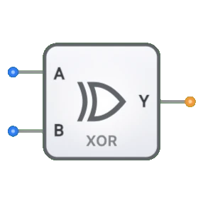
- シンボル: XORゲートは、入力側に二重曲線を持つシンボルで表され、通常のORゲートと区別されます。
- DigiSim.ioでの役割: 算術回路、コンパレータ、およびエラー検出システムを構築するための基本的なコンポーネントとして機能します。
機能説明
論理動作
XORゲートは排他的論理和を実装し、奇数個の入力がHIGHの場合にHIGH出力を生成します。
真理値表(2入力XORゲート):
| Input A | Input B | Output Y |
|---|---|---|
| 0 | 0 | 0 |
| 0 | 1 | 1 |
| 1 | 0 | 1 |
| 1 | 1 | 0 |
ブール式: Y = A ⊕ B(YはA XOR Bに等しい)
入力と出力
- 入力: XORゲートは2つの入力(A、B)を持ちます。
- 出力: XOR演算の結果を表す単一の1ビット出力。
DigiSim.ioでの視覚的表現
XORゲートは、左側に入力ピン、右側に出力ピンを配置して表示されます。そのシンボルには、ORゲートと区別するための特徴的な二重曲線が入力側にあります。回路に接続すると、接続ワイヤの色の変化を通じてピンの論理状態を視覚的に示します。
教育的価値
主要概念
- ブール代数: 独立したブール関数としての排他的OR演算を実証します。
- 組み合わせ論理: ゲートの出力が現在の入力値のみによって決定されることを示します。
- ビット比較: ビットが異なる場合を検出する概念を説明します。
- 算術演算: バイナリ加算回路でXORがどのように使用できるかを紹介します。
学習目標
- 排他的OR演算とその真理値表表現を理解する。
- 包含的OR(ORゲート)と排他的OR(XORゲート)の違いを学ぶ。
- XORゲートが算術回路、特にバイナリ加算にどのように使用されるかを認識する。
- エラー検出システムのパリティ生成/チェックにXORゲートを適用する。
使用例/シナリオ
- バイナリ加算: 半加算器回路では、XORゲートが2つのバイナリ入力の和ビットを生成します。
- パリティ生成/チェック: エラー検出のためのデータ伝送におけるパリティビットの作成または検証。
- ビットコンパレータ: 2つのバイナリ数の対応するビットが異なる場合の検出。
- 制御インバータ: 1つの制御入力を持つXORゲートを使用して信号を選択的に反転する。
技術ノート
- XORゲートの出力は、いずれかの入力がハイインピーダンス(high-Z)状態または未定義の場合、ハイインピーダンスを示します。
- DigiSim.ioでは基本論理ゲートですが、XORゲートは物理回路ではAND、OR、NOTゲートの組み合わせを使用して実装されることが一般的です。
- 多入力XORゲートの場合、奇数個の入力がHIGHの場合にのみ出力がHIGHになり、パリティ計算に有用です。
トランジスタレベルの実装
- CMOS:MOSFETの相補対を使用
- TTL:バイポーラ接合トランジスタを使用
集積回路
- 74xx86:クワッド2入力XORゲート
- 74xx266:クワッド2入力XNORゲート
トランスミッションゲート実装
- 相補型パストランジスタを使用
- 特定のアプリケーションで効率的
回路実装(基本ゲートを使用した2入力XOR)
graph LR
    A[Input A] --> NOT1[NOT Gate]
    B[Input B] --> NOT2[NOT Gate]

    NOT1 --> AND1[AND Gate]
    B --> AND1

    A --> AND2[AND Gate]
    NOT2 --> AND2

    AND1 --> OR[OR Gate]
    AND2 --> OR
    OR --> Y[Output Y]
ロジック: Y = A·B̄ + Ā·B(A XOR Bは入力が異なる場合にHIGHを生成)
ブール式
2入力XORゲートの場合:
- Y = A ⊕ B
- Y = A·B̄ + Ā·B
- Y = (A + B) · (Ā + B̄)
- Y = A ≠ B(不等号)
3入力XORゲートの場合:
- Y = A ⊕ B ⊕ C
- Y = A·B̄·C̄ + Ā·B·C̄ + Ā·B̄·C + A·B·C
関連コンポーネント
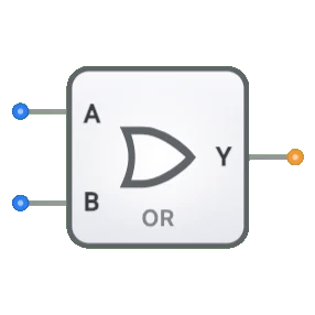
- ORゲート: いずれかの入力がtrueの場合にtrueを出力
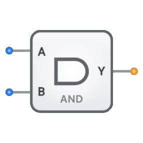
- ANDゲート: すべての入力がtrueの場合にのみtrueを出力
- XNORゲート: XORの補数、入力が等しい場合にtrueを出力
- 半加算器: バイナリ加算のためにXORゲートとANDゲートを組み合わせる
- 全加算器: 和の生成にXORゲートを使用
- パリティ生成器/チェッカー: エラー検出にXORゲートを使用
- マルチプレクサ: 適切な構成でXOR機能を実装可能
- 制御インバータ: 特定のアプリケーションで同様の機能