인코더
개요
- 목적: 인코더는 4대2 우선순위 인코더로, 활성 입력 신호를 가장 높은 우선순위의 활성 입력을 나타내는 이진 코드로 변환하는 조합 디지털 회로입니다. 디코더의 역방향 연산을 수행하여 4개의 입력 라인을 2비트 이진 코드로 줄입니다.
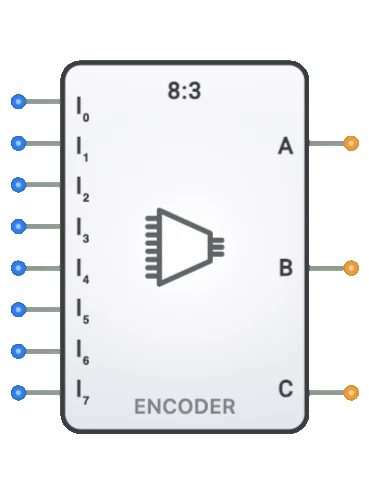
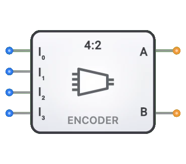
- 기호: 인코더는 4개의 입력 라인(D0, D1, D2, D3)과 2개의 출력 라인(Q0, Q1)이 있는 직사각형 블록으로 표현됩니다.
- DigiSim.io 역할: 디지털 회로에서 우선순위 감지, 주소 생성 및 입력 인코딩을 위한 기본 빌딩 블록으로 사용됩니다.
기능 설명
논리 동작
인코더는 가장 높은 우선순위의 활성 입력의 이진 코드를 출력하는 우선순위 인코더입니다. 여러 입력이 동시에 활성화되면 인코더는 가장 높은 번호의 활성 입력에 대한 코드를 출력합니다. 낮은 우선순위의 입력은 무관 조건(X)으로 처리됩니다.
진리표 (4대2 우선순위 인코더):
| D3 | D2 | D1 | D0 | Q1 | Q0 |
|---|---|---|---|---|---|
| 0 | 0 | 0 | 1 | 0 | 0 |
| 0 | 0 | 1 | X | 0 | 1 |
| 0 | 1 | X | X | 1 | 0 |
| 1 | X | X | X | 1 | 1 |
입력 및 출력
입력:
- 4개의 데이터 입력(D0, D1, D2, D3): 네 개의 입력 라인으로, D3이 가장 높은 우선순위를, D0이 가장 낮은 우선순위를 가집니다.
출력:
- 2개의 이진 출력(Q0, Q1): 가장 높은 우선순위의 활성 입력을 나타내는 2비트 이진 코드.
구성 가능한 매개변수
- 우선순위 처리: 인코더는 우선순위 해석을 사용합니다. 여러 입력이 활성화되면 가장 높은 번호의 입력이 우선합니다.
- 전파 지연: 입력 변경 후 출력이 변경되는 데 걸리는 시간.
DigiSim.io에서의 시각적 표현
인코더는 한쪽에 4개의 입력 핀(D0-D3)과 반대쪽에 2개의 출력 핀(Q0, Q1)이 있는 직사각형 블록으로 표시됩니다. 회로에 연결되면 구성 요소는 연결 와이어의 색상 변화를 통해 활성 입력과 결과 이진 코드를 시각적으로 나타냅니다.
교육적 가치
핵심 개념
- 이진 인코딩: 여러 신호가 간결한 이진 형태로 인코딩될 수 있는 방법을 보여줍니다.
- 데이터 압축: 여러 신호 라인이 더 적은 라인으로 줄일 수 있는 방법을 설명합니다.
- 원-핫에서 이진 변환: 원-핫과 이진 표현 간의 관계를 보여줍니다.
- 조합 논리 설계: 인코딩 기능을 위한 논리 회로 설계를 소개합니다.
학습 목표
- 여러 입력 신호가 이진 형식으로 인코딩될 수 있는 방법을 이해합니다.
- 인코더와 디코더가 상보적 구성 요소로서의 관계를 학습합니다.
- 기본 인코더와 우선순위 인코더의 차이를 인식합니다.
- 입력 처리 시스템 및 주소 생성기 설계에 인코더를 적용합니다.
- 인코더가 디지털 시스템에서 신호 라인 수를 효율적으로 줄일 수 있는 방법을 이해합니다.
사용 예시/시나리오
- 키패드 인코딩: 키패드 버튼 누름을 이진 코드로 변환.
- 우선순위 감지: 우선순위 요구 사항이 있는 시스템에서 가장 높은 우선순위의 활성 입력 식별.
- 주소 생성: 원-핫 선택 신호에서 이진 주소 생성.
- 입력 처리: 다양한 입력 형식을 표준화된 이진 코드로 변환.
- 제어 시스템: 여러 상태 신호를 처리를 위한 간결한 형태로 인코딩.
기술 참고사항
- DigiSim.io 인코더는 우선순위 인코더입니다: 여러 입력이 활성화되면 가장 높은 우선순위(가장 높은 번호)의 활성 입력의 이진 코드를 출력합니다.
- 4대2 구성은 4개의 입력(D0-D3)을 사용하고 2비트 이진 출력(Q0, Q1)을 생성합니다.
- DigiSim.io에서 인코더는 입력 변경에 즉시 응답하여 우선순위 인코더의 조합 논리 동작을 모델링합니다.
특성
- 입력 크기: 4개의 입력 라인(D0-D3)
- 출력 크기: 2개의 출력 라인(Q0, Q1)
- 전파 지연: 입력 변경과 안정적인 출력 사이의 시간 지연
- 팬인: 인코더가 처리할 수 있는 입력 라인 수
- 팬아웃: 각 출력이 구동할 수 있는 논리 게이트 수
- 입력 유효성 검사: 유효/무효 입력을 감지하는 선택적 기능
- 활성화 제어: 일부 인코더에는 동작을 제어하는 활성화 입력 포함
- 입력 우선순위: 인코더가 입력 간 우선순위를 준수하는지 여부
- 소비 전력: 동작 중 에너지 사용량
인코더의 종류
기본 인코더
- 우선순위 또는 유효성 검사 기능이 없는 간단한 인코더
- 한 번에 하나의 입력만 활성화된다고 가정
우선순위 인코더
- 우선순위에 따라 여러 활성 입력을 해결
- 가장 높은 우선순위 입력에 대한 코드 출력
- 종종 "유효 입력" 출력 플래그 포함
십진수-BCD 인코더
- 십진수를 이진화 십진수로 변환하는 10대4 인코더
- 숫자 디스플레이 및 키패드 애플리케이션에 사용
8진수-이진 인코더
- 8진수를 이진으로 변환하는 8대3 인코더
- 컴퓨팅 시스템에서 일반적
16진수-이진 인코더
- 16진수를 이진으로 변환하는 16대4 인코더
- 주소 디코딩 애플리케이션에 사용
키보드 인코더
- 키패드 또는 키보드 입력을 위한 특수 인코더
- 키 누름을 이진 코드로 변환
응용
주소 생성
- 원-핫 신호를 이진 주소로 변환
- 디지털 시스템에서의 메모리 주소 지정
입력 주변 장치
- 키보드 및 키패드 입력 인코딩
- 스위치 배열에서 이진으로의 변환
명령어 디코딩
- CPU에서의 명령어 패턴 인코딩
- 연산 코드 생성
제어 시스템
- 제어 애플리케이션을 위한 상태 인코딩
- 모드 선택 인코딩
디지털 멀티플렉싱
- 멀티플렉서 제어를 위한 주소 선택
- 통신 시스템에서의 채널 선택
데이터 압축
- 여러 신호 라인을 더 적은 라인으로 줄이기
- 병렬 데이터를 더 간결한 형식으로 변환
구현 방법
논리 게이트 배열
- 출력 비트 패턴에 따라 입력을 결합하기 위한 OR 게이트 사용
- 이산 부품 또는 IC 형태로 구현 가능
집적 회로
- 74148: 8대3 우선순위 인코더
- 74147: 10대4 십진수-BCD 우선순위 인코더
- 74LS348: 활성화가 있는 8대3 우선순위 인코더
HDL 설계
- Case 문 또는 조건부 할당
- 우선순위 인코더를 위한 우선순위 if-else 체인
- 다양한 크기로 쉽게 매개변수화
ROM 기반 구현
- ROM에 저장된 룩업 테이블 사용
- 복잡한 인코딩 체계에 적합
회로 구현 (4대2 우선순위 인코더)
4대2 우선순위 인코더는 우선순위 논리가 있는 OR 게이트를 사용하여 구현할 수 있습니다:
graph LR
    D1[D1] --> OR0[OR Gate]
    D3[D3] --> OR0
    OR0 --> Q0[Q0 Output]

    D2[D2] --> OR1[OR Gate]
    D3 --> OR1
    OR1 --> Q1[Q1 Output]
논리: D1 또는 D3이 가장 높은 우선순위의 활성 입력일 때 Q0이 HIGH입니다. D2 또는 D3이 가장 높은 우선순위의 활성 입력일 때 Q1이 HIGH입니다.
부울 표현식 (4대2 우선순위 인코더)
4대2 우선순위 인코더의 경우:
Q0 = D1·D̄2·D̄3 + D3
Q1 = D2·D̄3 + D3
간소화(우선순위 논리가 가장 높은 번호의 활성 입력이 우선하도록 보장):
Q0 = D3 + D1·D̄2
Q1 = D3 + D2
여기서 +는 논리 OR, ·는 논리 AND, D̄는 NOT을 나타냅니다
관련 구성 요소
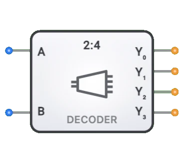
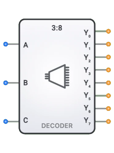
- 디코더: 역방향 연산 수행(이진에서 원-핫으로)
- 멀티플렉서: 데이터 선택을 위해 인코더와 함께 사용
- 디멀티플렉서: 데이터 분배를 위해 디코더와 함께 사용
- 우선순위 중재기: 우선순위 인코더와 유사하지만 다른 출력 형식
- 코드 변환기: 다양한 인코딩 체계 간의 변환
- 이진 카운터: 상태 감지를 위해 종종 인코더 사용
- 비교기: 때때로 인코더 원리를 사용하여 구현
- 주소 디코더: 메모리 시스템에서 사용되는 역방향 연산