Encodeur
Vue d'ensemble
- Objectif : L'encodeur est un encodeur prioritaire 4 vers 2 — un circuit numérique combinatoire qui convertit des signaux d'entrée actifs en un code binaire représentant l'entrée active de plus haute priorité. Il effectue l'opération inverse d'un décodeur, réduisant 4 lignes d'entrée à un code binaire de 2 bits.
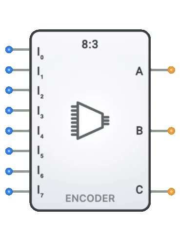
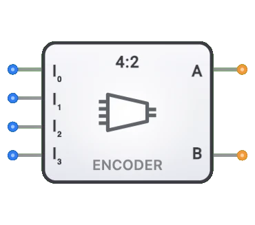
- Symbole : L'encodeur est représenté par un bloc rectangulaire avec 4 lignes d'entrée (D0, D1, D2, D3) et 2 lignes de sortie (Q0, Q1).
- Rôle dans DigiSim.io : Sert de bloc de construction fondamental pour la détection de priorité, la génération d'adresses et l'encodage d'entrées dans les circuits numériques.
Description fonctionnelle
Comportement logique
L'encodeur est un encodeur prioritaire qui produit le code binaire de l'entrée active de plus haute priorité. Lorsque plusieurs entrées sont actives simultanément, l'encodeur produit le code de l'entrée active de plus haut numéro — les entrées de priorité inférieure sont traitées comme indifférentes (X).
Table de vérité (encodeur prioritaire 4 vers 2) :
| D3 | D2 | D1 | D0 | Q1 | Q0 |
|---|---|---|---|---|---|
| 0 | 0 | 0 | 1 | 0 | 0 |
| 0 | 0 | 1 | X | 0 | 1 |
| 0 | 1 | X | X | 1 | 0 |
| 1 | X | X | X | 1 | 1 |
Entrées et sorties
Entrées :
- 4 entrées de données (D0, D1, D2, D3) : quatre lignes d'entrée, où D3 a la priorité la plus élevée et D0 la plus basse.
Sorties :
- 2 sorties binaires (Q0, Q1) : code binaire 2 bits représentant l'entrée active de plus haute priorité.
Paramètres configurables
- Gestion de la priorité : l'encodeur utilise une résolution de priorité — lorsque plusieurs entrées sont actives, l'entrée de plus haut numéro l'emporte.
- Délai de propagation : temps nécessaire pour que les sorties changent après une modification des entrées.
Représentation visuelle dans DigiSim.io
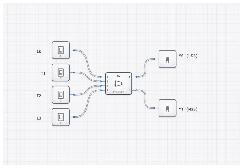
L'encodeur est affiché sous la forme d'un bloc rectangulaire avec 4 broches d'entrée (D0–D3) sur un côté et 2 broches de sortie (Q0, Q1) sur le côté opposé. Une fois connecté dans un circuit, le composant indique visuellement les entrées actives et le code binaire résultant sur les sorties par des changements de couleur sur les fils de connexion.
Valeur pédagogique
Concepts clés
- Encodage binaire : démontre comment plusieurs signaux peuvent être encodés sous forme binaire compacte.
- Compression de données : illustre comment plusieurs lignes de signal peuvent être réduites à moins de lignes.
- Conversion one-hot vers binaire : montre la relation entre les représentations one-hot et binaires.
- Conception de logique combinatoire : introduit la conception de circuits logiques pour les fonctions d'encodage.
Objectifs d'apprentissage
- Comprendre comment plusieurs signaux d'entrée peuvent être encodés au format binaire.
- Apprendre la relation entre encodeurs et décodeurs en tant que composants complémentaires.
- Reconnaître la différence entre les encodeurs de base et les encodeurs prioritaires.
- Appliquer les encodeurs à la conception de systèmes de traitement d'entrées et de générateurs d'adresses.
- Comprendre comment les encodeurs peuvent réduire efficacement le nombre de lignes de signaux dans les systèmes numériques.
Exemples d'utilisation / Scénarios
- Encodage de clavier matriciel : convertir des appuis de touches en codes binaires.
- Détection de priorité : identifier l'entrée active de plus haute priorité dans des systèmes nécessitant une priorisation.
- Génération d'adresses : créer des adresses binaires à partir de signaux de sélection one-hot.
- Traitement d'entrées : convertir divers formats d'entrée en codes binaires standardisés.
- Systèmes de commande : encoder plusieurs signaux d'état sous forme compacte pour le traitement.
Notes techniques
- L'encodeur DigiSim.io est un encodeur prioritaire : lorsque plusieurs entrées sont actives, il produit le code binaire de l'entrée active de plus haute priorité (numéro le plus élevé).
- La configuration 4 vers 2 utilise 4 entrées (D0–D3) et produit une sortie binaire 2 bits (Q0, Q1).
- Dans DigiSim.io, l'encodeur réagit immédiatement aux changements d'entrée, modélisant le comportement combinatoire des encodeurs prioritaires.
Caractéristiques
- Taille d'entrée : 4 lignes d'entrée (D0–D3)
- Taille de sortie : 2 lignes de sortie (Q0, Q1)
- Délai de propagation : délai entre un changement d'entrée et la stabilisation de la sortie
- Fan-In : nombre de lignes d'entrée que l'encodeur peut gérer
- Fan-Out : nombre de portes logiques que chaque sortie peut piloter
- Validation d'entrée : fonctionnalité optionnelle pour détecter les entrées valides/non valides
- Commande d'activation : certains encodeurs incluent des entrées d'activation pour contrôler le fonctionnement
- Priorité d'entrée : indique si l'encodeur respecte une priorité parmi les entrées
- Consommation électrique : énergie consommée pendant le fonctionnement
Types d'encodeurs
Encodeurs de base
- Encodeur simple sans fonctionnalité de priorité ou de validation
- Suppose qu'une seule entrée est active à la fois
Encodeurs prioritaires
- Résout plusieurs entrées actives selon leur priorité
- Produit le code de l'entrée de plus haute priorité
- Inclut souvent un drapeau de sortie « entrée valide »
Encodeurs décimal vers BCD
- Encodeurs 10 vers 4 pour la conversion décimal vers BCD
- Utilisés dans les applications d'affichage numérique et de claviers
Encodeurs octal vers binaire
- Encodeurs 8 vers 3 pour la conversion octal vers binaire
- Courants dans les systèmes informatiques
Encodeurs hexadécimal vers binaire
- Encodeurs 16 vers 4 pour la conversion hexadécimal vers binaire
- Utilisés dans les applications de décodage d'adresses
Encodeurs de clavier
- Encodeurs spécialisés pour les entrées de clavier matriciel ou d'ordinateur
- Convertissent les appuis de touches en codes binaires
Applications
Génération d'adresses
- Conversion de signaux one-hot en adresses binaires
- Adressage mémoire dans les systèmes numériques
Périphériques d'entrée
- Encodage d'entrée de claviers d'ordinateur ou matriciels
- Conversion de matrices d'interrupteurs en binaire
Décodage d'instructions
- Encodage de motifs d'instruction dans les CPU
- Génération de codes d'opération
Systèmes de commande
- Encodage d'état pour les applications de commande
- Encodage de sélection de mode
Multiplexage numérique
- Sélection d'adresses pour la commande de multiplexeurs
- Sélection de canaux dans les systèmes de communication
Compression de données
- Réduction du nombre de lignes de signaux
- Conversion de données parallèles en formats plus compacts
Méthodes de mise en œuvre
Réseaux de portes logiques
- Utilisation de portes OU pour combiner les entrées selon les motifs de bits de sortie
- Peut être implémenté avec des composants discrets ou sous forme de CI
Circuits intégrés
- 74148 : encodeur prioritaire 8 vers 3
- 74147 : encodeur prioritaire décimal vers BCD 10 vers 4
- 74LS348 : encodeur prioritaire 8 vers 3 avec enable
Conception HDL
- Instructions case ou assignations conditionnelles
- Chaînes if-else prioritaires pour les encodeurs prioritaires
- Aisément paramétrable pour différentes tailles
Implémentation à base de ROM
- Utilisation de tables de correspondance stockées en ROM
- Adaptée aux schémas d'encodage complexes
Implémentation du circuit (encodeur prioritaire 4 vers 2)
Un encodeur prioritaire 4 vers 2 peut être implémenté à l'aide de portes OU avec une logique de priorité :
graph LR
    D1[D1] --> OR0[Porte OR]
    D3[D3] --> OR0
    OR0 --> Q0[Q0 Sortie]

    D2[D2] --> OR1[Porte OR]
    D3 --> OR1
    OR1 --> Q1[Q1 Sortie]
Logique : Q0 est HIGH lorsque D1 ou D3 est l'entrée active de plus haute priorité. Q1 est HIGH lorsque D2 ou D3 est l'entrée active de plus haute priorité.
Équations booléennes (encodeur prioritaire 4 vers 2)
Pour l'encodeur prioritaire 4 vers 2 :
Q0 = D1·D̄2·D̄3 + D3
Q1 = D2·D̄3 + D3
Simplifié (la logique de priorité garantit que l'entrée active de plus haut numéro l'emporte) :
Q0 = D3 + D1·D̄2
Q1 = D3 + D2
Où + représente le OU logique, · représente le ET logique et D̄ représente le NON
Composants associés
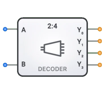
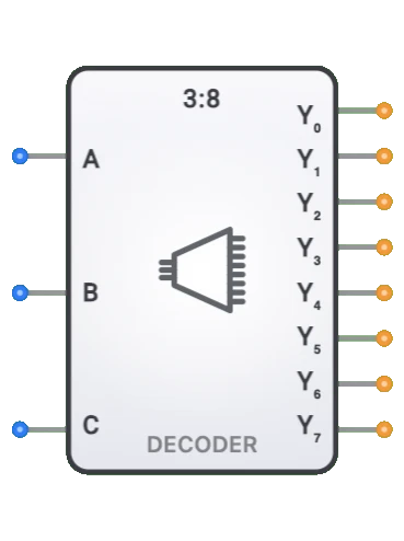
- Décodeurs : effectuent l'opération inverse (binaire vers one-hot)
- Multiplexeurs : utilisés avec les encodeurs pour la sélection de données
- Démultiplexeurs : utilisés avec les décodeurs pour la distribution de données
- Arbitres prioritaires : similaires aux encodeurs prioritaires mais avec un format de sortie différent
- Convertisseurs de codes : transforment entre différents schémas d'encodage
- Compteurs binaires : utilisent souvent des encodeurs pour la détection d'état
- Comparateurs : parfois implémentés selon des principes d'encodeur
- Décodeurs d'adresses : opération inverse utilisée dans les systèmes mémoire