Multiplexers (MUX) Demystified: The Data Traffic Controller
A multiplexer routes one of $2^n$ inputs to a single output via n select lines. Build 2-to-1 and 4-to-1 MUXes and use them as universal function generators.

TL;DR: A multiplexer (MUX) selects one of data inputs and routes it to a single output, controlled by select lines. The Boolean expression for a 4-to-1 MUX is . A MUX can also serve as a universal function generator — the building block of FPGA lookup tables.
A CPU register file uses MUXes to choose which register feeds the ALU. A TV uses one to select an input. An FPGA uses thousands of them as programmable lookup tables. The multiplexer (MUX) is one of the most versatile combinational circuits — this guide covers the Boolean foundation, gate-level construction, cascading, and the universal-function-generator property.
What is a Multiplexer?
A multiplexer is a combinational circuit that selects one of several data inputs and forwards it to a single output line. The selection is controlled by a separate set of select lines that encode a binary address corresponding to the desired input.
The fundamental relationship governing all multiplexers is:
select lines can choose from data inputs.
This means a MUX with 1 select line handles 2 inputs. With 2 select lines, it handles 4. With 3, it handles 8. This exponential scaling makes the MUX an extraordinarily compact data routing device.
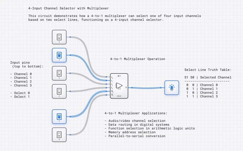
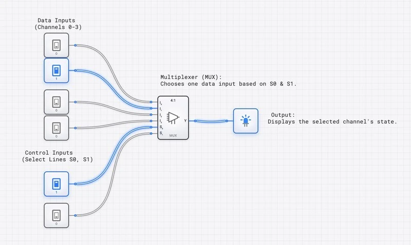
A 4-to-1 multiplexer: 2 select lines choose between 4 inputs. The selected input appears at the output.
The 2-to-1 MUX: The Simplest Data Selector
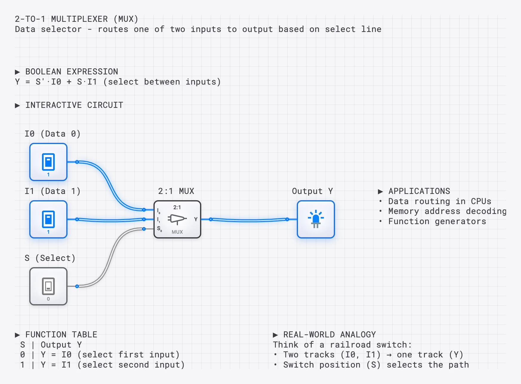
The 2-to-1 MUX is the fundamental building block. It has 2 data inputs (, ), 1 select line (), and 1 output ().
| Select () | Output () |
|---|---|
| 0 | |
| 1 |
The Boolean expression is straightforward. We need to pass through when and to pass through when :
To implement this with basic gates, you need:
- One NOT gate to produce
- Two AND gates: one computes , the other computes
- One OR gate to combine both AND outputs into the final result
A 2-to-1 MUX built from AND, OR, and NOT gates. When S=0, passes through; when S=1, passes through.
The 4-to-1 MUX: Boolean Expression and Gate-Level Design
A 4-to-1 MUX has 4 data inputs ( through ) and 2 select lines (, ). The select lines form a 2-bit binary address that chooses which input reaches the output.
| Output () | ||
|---|---|---|
| 0 | 0 | |
| 0 | 1 | |
| 1 | 0 | |
| 1 | 1 |
Each row of this table corresponds to one product term where the select lines “enable” exactly one data input. The complete Boolean expression for the 4-to-1 MUX is:
This expression tells us exactly what hardware we need:
- 2 NOT gates to produce and
- 4 three-input AND gates, each gating one data input with the appropriate select combination
- 1 four-input OR gate to combine all four AND outputs
The total gate count is 7 gates (2 NOT + 4 AND + 1 OR). Each AND gate acts as a “gatekeeper,” allowing its associated data input to pass only when the select lines match its assigned binary address.
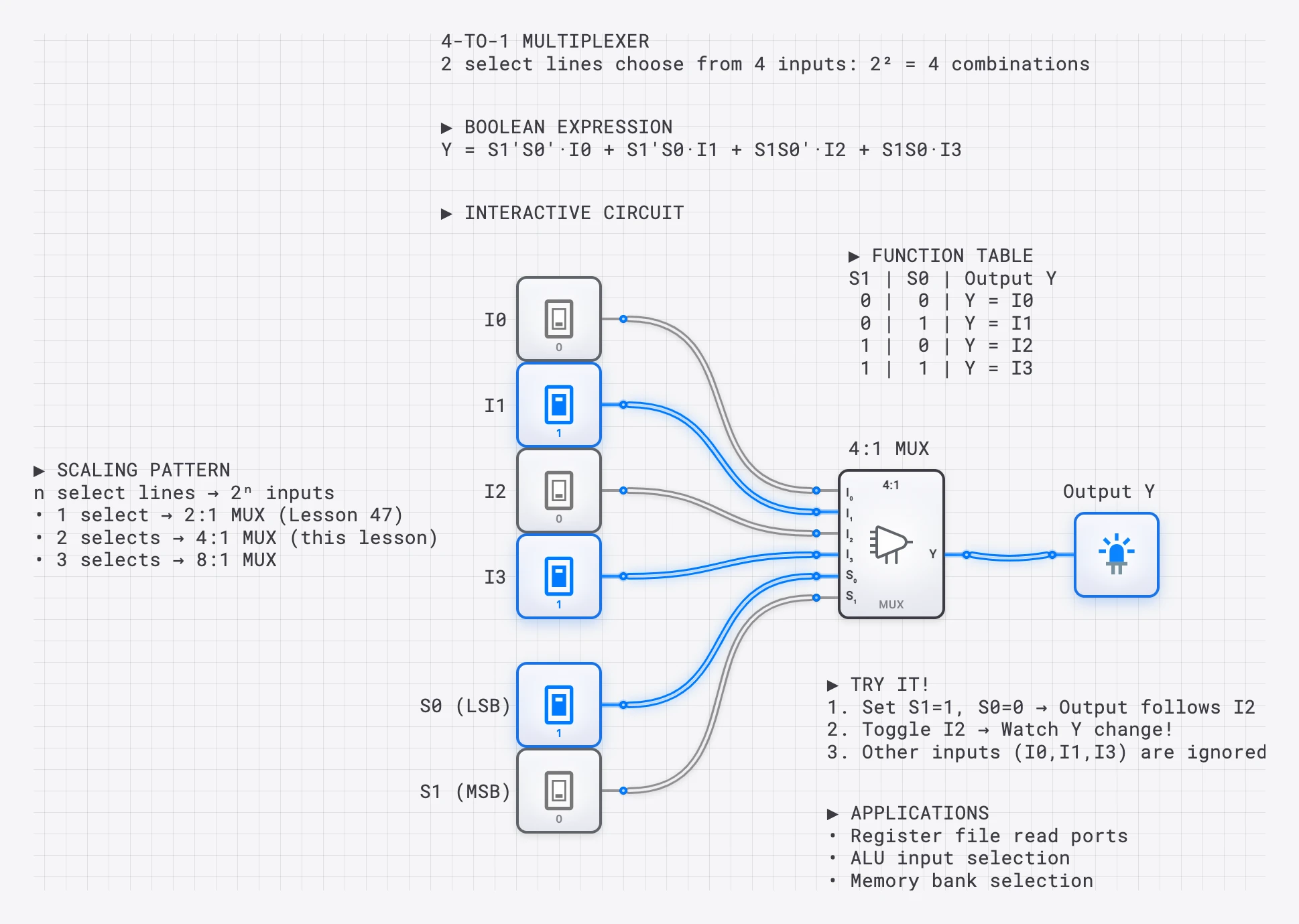
4-to-1 MUX with function table and scaling pattern. select lines choose from inputs.
Building a 4-to-1 MUX on digisim.io
Follow these steps to build a 4-to-1 MUX from discrete gates:
- Place the select lines. Drag two INPUT_SWITCH components onto the canvas and label them and .
- Generate the complements. Place two NOT gates. Connect to one and to the other, producing and .
- Place the data inputs. Add four INPUT_SWITCH components and label them , , , and .
- Create the AND array. Place four AND gates (3-input each):
- AND-0: inputs are , , and
- AND-1: inputs are , , and
- AND-2: inputs are , , and
- AND-3: inputs are , , and
- Combine the results. Place one OR gate and connect all four AND outputs to it. The OR output is your final output .
- Add visualization. Connect to an OUTPUT_LIGHT.
Toggle the select switches to route different data inputs to the output. Only one AND gate will produce a non-zero output at any time, and that value passes through the OR to become .
Cascading MUXes: Building an 8-to-1 from 4-to-1 Units
One of the most powerful properties of multiplexers is that they can be cascaded to handle more inputs. You do not need to design an 8-to-1 MUX from scratch; you can build it from smaller units.
An 8-to-1 MUX requires 3 select lines (, , ) and 8 data inputs ( through ). Here is how to construct it from two 4-to-1 MUXes and one 2-to-1 MUX:
- First stage (two 4-to-1 MUXes):
- MUX-A handles -, with and as its select lines.
- MUX-B handles -, with and as its select lines.
- Second stage (one 2-to-1 MUX):
- The output of MUX-A connects to of the final MUX.
- The output of MUX-B connects to of the final MUX.
- serves as the select line for this final MUX.
When , the final MUX passes the result from MUX-A (inputs -). When , it passes the result from MUX-B (inputs -). The lower select lines and determine which of the four inputs within the selected group reaches the output.
This hierarchical approach scales to any size. A 16-to-1 MUX can be built from two 8-to-1 MUXes and one 2-to-1, or from four 4-to-1 MUXes feeding a second-level 4-to-1 MUX.
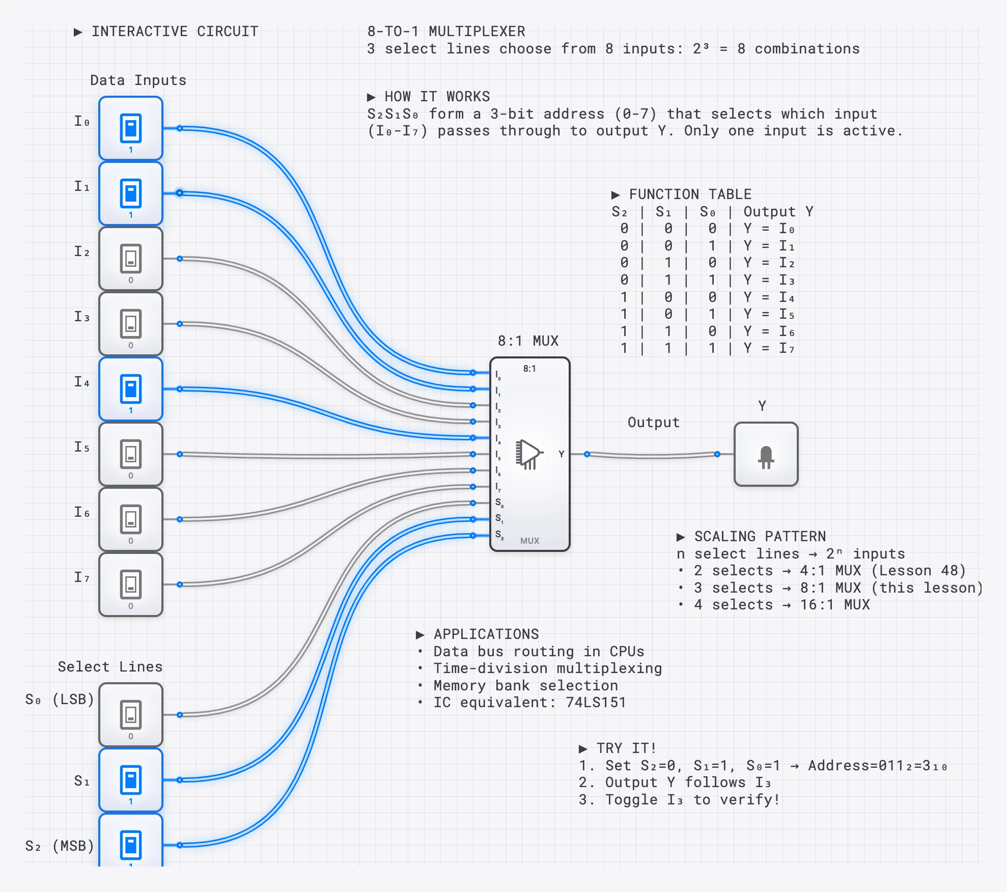
An 8-to-1 MUX with 3 select lines. This can be built from two 4-to-1 MUXes and one 2-to-1 MUX.
The MUX as a Universal Function Generator
Perhaps the most remarkable property of the multiplexer is that it can implement any Boolean function without using traditional logic gates. A -to-1 MUX can implement any function of variables by connecting the function’s input variables to the select lines and hardwiring the data inputs to 0 or 1 according to the function’s truth table.
For example, consider a 3-variable function . Using an 8-to-1 MUX:
- Connect , , and to the select lines , , and .
- For each row of the truth table, the select combination addresses one data input. Wire that data input to 1 if for that row, or to 0 if .
The MUX output will then produce the exact truth table of your function. This makes the MUX a universal function generator, a property exploited heavily in Field Programmable Gate Arrays (FPGAs), where lookup tables (LUTs) are essentially small MUXes that can be programmed to implement any logic function.
You can also use a smaller MUX by applying one input variable to the data lines instead of the select lines. For instance, a 3-variable function can be implemented with a 4-to-1 MUX (using only 2 select lines) by connecting and to the select lines and wiring each data input to 0, 1, , or as needed.
Worked Example: Implementing a Majority Function
The 3-input majority function outputs 1 when two or more inputs are 1. Its truth table is:
| 0 | 0 | 0 | 0 |
| 0 | 0 | 1 | 0 |
| 0 | 1 | 0 | 0 |
| 0 | 1 | 1 | 1 |
| 1 | 0 | 0 | 0 |
| 1 | 0 | 1 | 1 |
| 1 | 1 | 0 | 1 |
| 1 | 1 | 1 | 1 |
Using an 8-to-1 MUX: Connect , , to , , . Wire data inputs through to match the column: , , , , , , , . The MUX now implements the majority function with zero traditional logic gates.
Using a 4-to-1 MUX (reduced form): Connect and to and . Group the truth table rows by :
- : for both and . Wire .
- : when , when . Wire .
- : when , when . Wire .
- : for both and . Wire .
This implements the same function using a smaller MUX, with connected directly to two data inputs.
Propagation Delay and Timing Considerations
Like all combinational circuits, a MUX introduces propagation delay. The critical path through a 4-to-1 MUX built from discrete gates passes through one NOT gate, one AND gate, and one OR gate:
When MUXes are cascaded, the delays accumulate. A two-level cascade (e.g., the 8-to-1 built from 4-to-1 units) has roughly double the delay of a single-level MUX. For timing-critical paths in high-speed designs, wider single-level MUXes (built with wider AND and OR gates) may be preferred over cascaded smaller ones, trading gate count for speed.
In the digisim.io editor, you can observe this delay by connecting an OSCILLOSCOPE to both the select line input and the MUX output. When you toggle a select line, notice the brief delay before the output stabilizes at the newly selected input’s value. This settling time is the MUX’s propagation delay.
The General Boolean Expression for an -to-1 MUX
We can generalize the MUX Boolean expression to any size. For a -to-1 MUX with select lines and data inputs :
where is the -th minterm of the select variables. Each minterm is a product of all select variables, each appearing in either true or complemented form depending on the binary representation of . For instance, in an 8-to-1 MUX, the minterm for (binary 101) is .
This formulation makes it clear that a MUX is literally a hardware implementation of the sum-of-minterms canonical form. Every Boolean function has a unique sum-of-minterms expression, and a MUX can implement it directly by wiring the data inputs to the appropriate constant values.
The Enable Input
Many commercial MUX ICs include an enable pin, typically active-LOW and labeled . Asserting it (driving the pin LOW) lets the MUX pass data; de-asserting it (HIGH) forces the output to 0 (or high-impedance, for tri-state outputs). Internally we treat the gated signal as the active-HIGH form , so that “enabled” maps to :
This feature is essential for cascading MUXes and for tri-state bus architectures where only one device should drive the bus at a time.
When building cascaded MUXes on digisim.io, you can simulate the enable function by adding an AND gate between the final OR output and an enable switch.
Real-World Analogy: TV Channel Selector
Imagine you have 4 video sources (gaming console, cable box, Blu-ray, streaming stick) and one TV. A MUX is like the input selector: the remote’s button (select lines) determines which source appears on screen (output). The video data flows continuously from all four sources, but the MUX gates only the selected one through to the display.
TV channel selector as a MUX: select lines choose which input source appears on the TV.
The Demultiplexer (DEMUX)
The opposite of a MUX is a Demultiplexer (DEMUX). While a MUX selects one of many inputs and routes it to a single output, a DEMUX takes a single input and routes it to one of many outputs based on the select lines.
The Boolean expressions for a 1-to-4 DEMUX are:
Notice that a DEMUX is structurally identical to a decoder with an enable input. When the data input acts as the enable, the “address” on the select lines determines which output receives the signal.
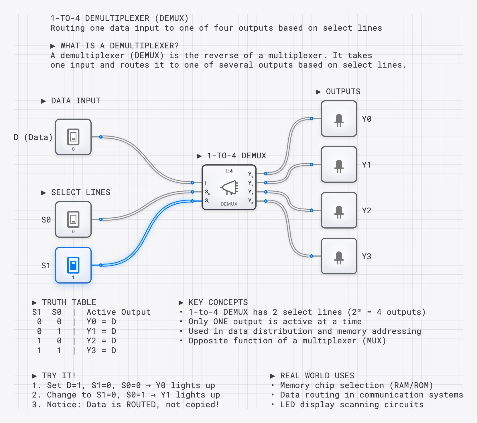
A 1-to-4 DEMUX: one input is routed to one of four outputs based on 2 select lines.
Applications of Multiplexers
Multiplexers appear at every level of digital system design. Here are the most important applications, with enough detail to understand why MUXes are indispensable.
CPU Register File
A CPU’s register file typically contains 8, 16, or 32 general-purpose registers. The ALU needs to read two operands simultaneously, which means the register file needs two independent read ports. Each read port is implemented as a wide MUX: for an 8-register file, each read port uses an 8-to-1 MUX (3-bit select) per bit of register width. For 8-bit registers with 8 locations, that is two 8-to-1 MUXes per bit, or 16 total MUXes just for the read ports. The register address fields from the instruction’s opcode drive the select lines, choosing which registers’ contents appear at the ALU inputs.
ALU Input Selection
The ALU’s operands do not always come from registers. Sometimes an operand is an immediate constant embedded in the instruction, or a value read from memory. A MUX at each ALU input allows the control unit to select the operand source: register file output, immediate value, or memory data register. This single MUX per ALU input gives the CPU the flexibility to execute register-register, register-immediate, and memory-register instructions using the same ALU hardware.
Memory Address Decoding and Bus Arbitration
When multiple memory banks or I/O devices share a data bus, MUXes route data from the selected device onto the bus. A decoder selects which device is active, and a MUX gates that device’s output onto the shared bus. Similarly, when multiple bus masters (CPU, DMA controller, GPU) compete for bus access, an arbitration circuit uses MUXes to grant access to one master at a time.
FPGA Lookup Tables
The fundamental logic element in most FPGAs is a lookup table (LUT), which is physically implemented as a small MUX (typically 16-to-1 for a 4-input LUT, or 64-to-1 for a 6-input LUT). The LUT’s SRAM cells store the truth table of the desired function, and the input variables drive the MUX select lines. This architecture allows any combinational function of variables to be implemented by simply programming the LUT’s memory contents, without changing any wiring. The multiplexer is therefore the literal building block of all reconfigurable computing.
Try It Yourself
Build these circuits in the digisim.io editor to solidify your understanding:
- Build a 2-to-1 MUX from 2 AND gates, 1 OR gate, and 1 NOT gate. Verify all four input combinations.
- Expand to a 4-to-1 MUX using the Boolean expression above. Connect an OSCILLOSCOPE to observe the output as you sweep through select combinations.
- Cascade two 4-to-1 MUXes and a 2-to-1 MUX to build an 8-to-1. Verify that all 8 inputs are individually addressable.
- Implement a Boolean function using a MUX. Pick any 3-variable function from a truth table and program it into an 8-to-1 MUX by hardwiring the data inputs.
- Build a DEMUX to reverse the routing: send one signal to one of four outputs.
Continue with decoders and encoders (the structural cousin of the DEMUX), see how MUXes feed the ALU in the fetch-decode-execute cycle, or open the AND gate component reference — the primary building block of every MUX.