Decoders and Encoders: Driving a 7-Segment Display
Decoders translate binary into one-hot or segment outputs; encoders do the reverse. Build a BCD-to-7-segment driver and learn priority encoders.

TL;DR: A decoder converts an n-bit input into one of one-hot outputs. An encoder does the inverse. A BCD-to-7-segment decoder is a special case: it activates multiple outputs at once to drive seven LED segments. Priority encoders resolve simultaneous inputs and underpin interrupt controllers.
Decoders and encoders are the translators of the digital world. A decoder converts compact binary codes into broader, human-readable signals. An encoder does the reverse, compressing many inputs into a compact binary representation. Together, they form the interface between the efficient binary language that machines prefer and the signals that humans and peripheral devices need.
In this guide, we will build a working BCD-to-7-segment display driver from Boolean expressions, understand the difference between common anode and common cathode displays, explore priority encoders and their role in interrupt handling, and construct these circuits on digisim.io.
What is a Decoder?
A decoder is a combinational circuit that takes an -bit binary input and activates exactly one of output lines. The input acts as an “address,” and the decoder selects the corresponding output, setting it HIGH while all other outputs remain LOW. This “one-hot” output encoding is the defining characteristic of a binary decoder.
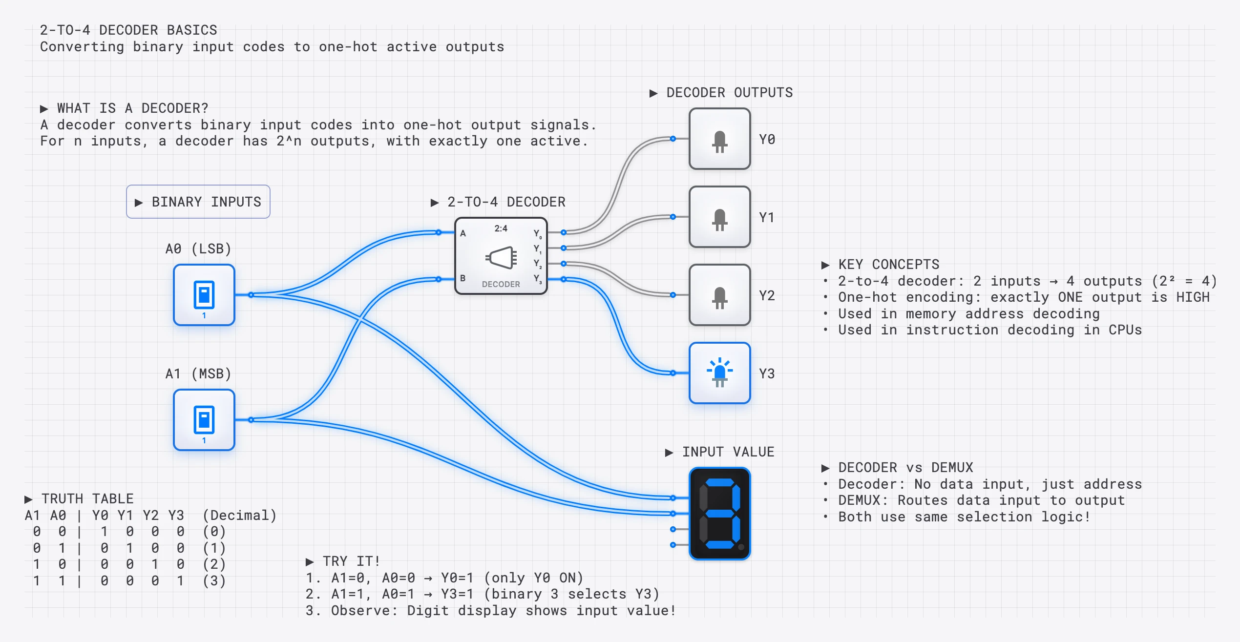
A 2-to-4 decoder: the 2-bit input selects which of 4 outputs is HIGH. Input 10 (binary 2) activates output .
The 2-to-4 Decoder: Truth Table and Boolean Expressions
| 0 | 0 | 1 | 0 | 0 | 0 |
| 0 | 1 | 0 | 1 | 0 | 0 |
| 1 | 0 | 0 | 0 | 1 | 0 |
| 1 | 1 | 0 | 0 | 0 | 1 |
Each output is a unique AND combination of the input variables (complemented or not):
To build a 2-to-4 decoder, you need 2 NOT gates and 4 two-input AND gates. Each AND gate receives a unique combination of the original and inverted input signals.
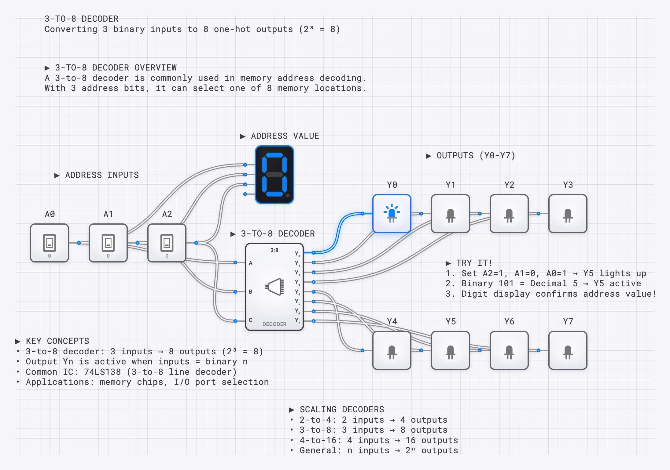
Scaling to Larger Decoders
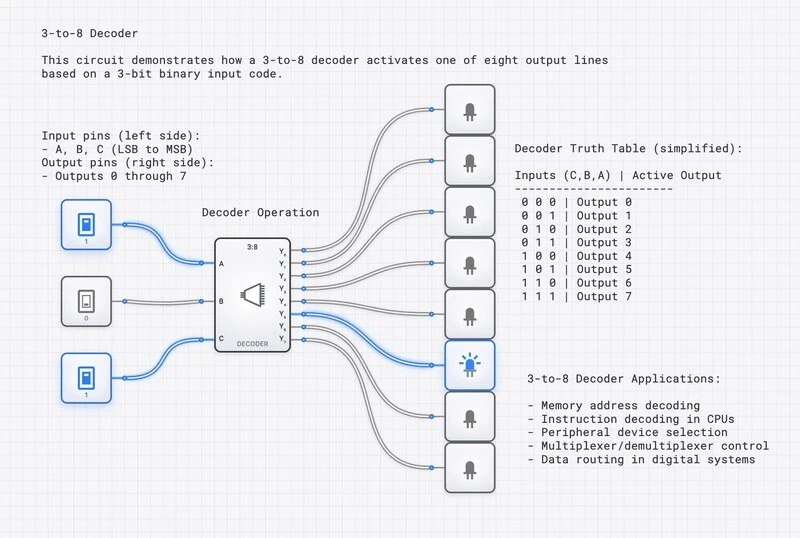
A 3-to-8 decoder follows the same pattern but uses 3-input AND gates for 8 outputs. Each output corresponds to one of the eight possible 3-bit input combinations. In general, an -to- decoder requires NOT gates and AND gates with inputs each.
A 3-to-8 decoder using AND gates. Each output requires a unique combination of inverted/non-inverted inputs.
The 7-Segment Display
A 7-segment display shows decimal digits using seven LED segments arranged in a figure-8 pattern. Each segment is labeled a through g:
 ━━━━━ (a)
│     │
(f)   (b)
│     │
 ━━━━━ (g)
│     │
(e)   (c)
│     │
 ━━━━━ (d)
To display any digit from 0 to 9, we selectively illuminate the appropriate combination of segments. For instance, the digit “7” requires segments a, b, and c to be on while d, e, f, and g remain off.
Common Cathode vs. Common Anode
There are two physical configurations for 7-segment displays, and the distinction matters when designing the driver circuit:
- Common Cathode: All segment LEDs share a common ground (cathode) connection. A segment lights up when its anode is driven HIGH. In this configuration, the decoder outputs are active-HIGH: a logic 1 turns a segment on.
- Common Anode: All segment LEDs share a common positive supply (anode) connection. A segment lights up when its cathode is pulled LOW. In this configuration, the decoder outputs must be active-LOW: a logic 0 turns a segment on.
Most educational examples (and the digisim.io 7-segment component) use the common cathode convention, where a HIGH output illuminates the segment. If you are designing for a common anode display, simply invert all seven output signals.
Key Insight: This is NOT a Simple Decoder
A 7-segment decoder is fundamentally different from a standard binary decoder. A 4-to-16 decoder activates exactly ONE output at a time. A 7-segment decoder activates MULTIPLE segments simultaneously (the digit “8” lights all 7 segments). It is a combinational logic circuit with 7 independent output functions, each derived from the same 4-bit BCD input.
BCD-to-7-Segment: Truth Table
BCD (Binary Coded Decimal) uses 4 bits to represent the digits 0 through 9. The decoder maps each digit to the appropriate segment pattern:
| Digit | a | b | c | d | e | f | g | ||||
|---|---|---|---|---|---|---|---|---|---|---|---|
| 0 | 0 | 0 | 0 | 0 | 1 | 1 | 1 | 1 | 1 | 1 | 0 |
| 1 | 0 | 0 | 0 | 1 | 0 | 1 | 1 | 0 | 0 | 0 | 0 |
| 2 | 0 | 0 | 1 | 0 | 1 | 1 | 0 | 1 | 1 | 0 | 1 |
| 3 | 0 | 0 | 1 | 1 | 1 | 1 | 1 | 1 | 0 | 0 | 1 |
| 4 | 0 | 1 | 0 | 0 | 0 | 1 | 1 | 0 | 0 | 1 | 1 |
| 5 | 0 | 1 | 0 | 1 | 1 | 0 | 1 | 1 | 0 | 1 | 1 |
| 6 | 0 | 1 | 1 | 0 | 1 | 0 | 1 | 1 | 1 | 1 | 1 |
| 7 | 0 | 1 | 1 | 1 | 1 | 1 | 1 | 0 | 0 | 0 | 0 |
| 8 | 1 | 0 | 0 | 0 | 1 | 1 | 1 | 1 | 1 | 1 | 1 |
| 9 | 1 | 0 | 0 | 1 | 1 | 1 | 1 | 1 | 0 | 1 | 1 |
BCD values 10 through 15 (1010 to 1111) are invalid and typically produce blanked or undefined output.
A BCD to 7-segment decoder: 4-bit binary input produces 7 outputs to control each segment.
Deriving Boolean Expressions for Segment Outputs
Each of the seven segments has its own Boolean function of the four BCD inputs , , , . To derive these expressions, we look at which digits illuminate each segment and write the sum-of-products (or use Karnaugh maps for minimization).
Segment a (top horizontal)
Segment a is ON for digits 0, 2, 3, 5, 6, 7, 8, 9 and OFF for digits 1 and 4. Listing the minterms where :
After minimization using a Karnaugh map (treating BCD inputs 10-15 as don’t-cares), this simplifies to:
Or equivalently: (the XNOR of and ).
Segment g (middle horizontal)
Segment g is ON for digits 2, 3, 4, 5, 6, 8, 9 and OFF for digits 0, 1, 7. The minimized expression is:
Or expanded: .
Segment d (bottom horizontal)
Segment d is ON for digits 0, 2, 3, 5, 6, 8, 9 and OFF for digits 1, 4, 7. The minimized expression is:
The remaining four segments (b, c, e, f) are derived using the same process: list the minterms from the truth table, plot them on a Karnaugh map, and extract the minimized sum-of-products expression. In practice, the classic 7447 TTL IC (common anode, active-LOW outputs) and 7448 IC (common cathode, active-HIGH outputs) implement all seven of these functions internally.
Handling Invalid BCD Inputs
BCD only uses input values 0 through 9, but a 4-bit input can represent values 10 through 15. What should the display show for these invalid inputs? There are three common approaches:
- Blank the display: All segments off. This is the safest approach for production designs.
- Don’t-care treatment: During Karnaugh map minimization, treat inputs 10-15 as don’t-cares (). This produces simpler Boolean expressions (fewer gates) but may display unpredictable patterns for invalid inputs.
- Display hex digits: For hexadecimal displays, inputs 10-15 map to letters A through F, requiring additional segment patterns.
The expressions we derived above used the don’t-care approach, which is standard for BCD decoders.
Complete BCD to 7-segment decoder with active display showing the digit “5”.
Building a 7-Segment Driver on digisim.io
Follow these steps to build a working display driver:
- Place the BCD inputs. Add four INPUT_SWITCH components and label them , , , and .
- Generate complements. Place four NOT gates to produce , , , and .
- Build the segment logic. For each segment (a through g), implement its Boolean expression using AND and OR gates. Start with segment a using the minimized expression above.
- Connect to the display. Place a SEVEN_SEGMENT_DISPLAY component and wire each segment output to the corresponding segment input on the display.
- Test systematically. Toggle the input switches through all BCD values 0000 to 1001 and verify that the correct digit appears for each input.
For a shortcut, you can also use the pre-built BCD_TO_7SEG component in digisim.io, but building it from gates is the best way to understand how each segment’s logic is derived from the truth table.
What is an Encoder?
An encoder performs the inverse operation of a decoder. It takes input lines (of which at most one should be active) and produces an -bit binary code identifying which input is active.
| Function | Decoder | Encoder |
|---|---|---|
| Direction | Binary code to one-hot | One-hot to binary code |
| Input | bits | lines |
| Output | lines | bits |
| Example | Address to memory chip select | Keyboard key to scan code |
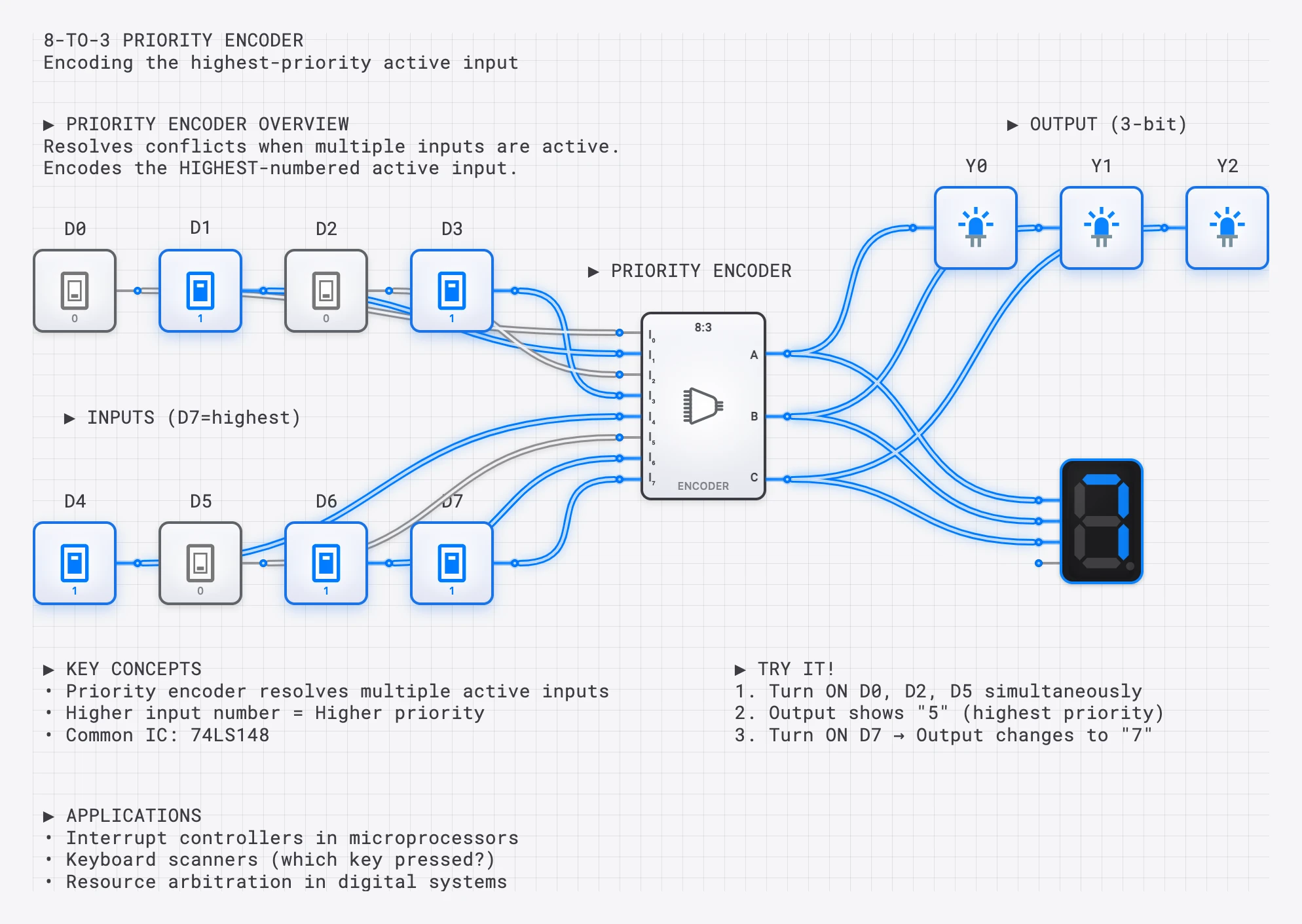
A 4-to-2 priority encoder: when multiple inputs are active, it encodes the HIGHEST priority one.
Simple 4-to-2 Encoder
A basic 4-to-2 encoder has 4 inputs (, , , ) and 2 outputs (, ). The Boolean expressions are:
This works correctly only if exactly one input is active at a time. If multiple inputs are active simultaneously, the output becomes ambiguous.
Priority Encoders
In real systems, multiple inputs can be active simultaneously. A priority encoder resolves this ambiguity by encoding only the highest-priority active input (typically the one with the highest index).
| Valid | Encoded Input | ||||||
|---|---|---|---|---|---|---|---|
| 0 | 0 | 0 | 0 | X | X | 0 | None |
| 0 | 0 | 0 | 1 | 0 | 0 | 1 | |
| 0 | 0 | 1 | X | 0 | 1 | 1 | |
| 0 | 1 | X | X | 1 | 0 | 1 | |
| 1 | X | X | X | 1 | 1 | 1 | (highest priority) |
The X entries mean “don’t care.” Lower-priority inputs are ignored whenever a higher-priority input is active. The Valid output indicates whether any input is active at all, which is important for downstream logic that needs to distinguish “input 0 is active” from “no input is active.”
Priority Encoder in Interrupt Handling
One of the most important applications of priority encoders is in interrupt controllers. In a microprocessor system, multiple hardware devices (keyboard, network card, timer, disk drive) can request the CPU’s attention simultaneously by asserting interrupt request lines.
A priority encoder connected to these interrupt lines performs three critical functions:
- Identifies the highest-priority interrupt. The device with the highest-priority request is encoded into a binary interrupt vector.
- Generates the interrupt vector. This binary code is sent to the CPU, which uses it to look up the correct interrupt service routine (ISR) address in an interrupt vector table.
- Masks lower-priority requests. While the CPU services the high-priority interrupt, lower-priority requests are held pending.
For example, the Intel 8259A Programmable Interrupt Controller (PIC), used in the original IBM PC architecture, is essentially a sophisticated 8-input priority encoder with programmable priority levels and masking capabilities.
Building a 3-to-8 Decoder on digisim.io
Here is a step-by-step guide to building a complete 3-to-8 decoder:
- Place the inputs. Add three INPUT_SWITCH components labeled , , and .
- Generate complements. Place three NOT gates for , , and .
- Build the AND array. Place eight 3-input AND gates. Each gate receives a unique combination of original and complemented inputs:
- …continuing through…
- Add outputs. Connect each AND output to an OUTPUT_LIGHT. As you toggle the inputs, exactly one light should be on at any time.
- Add an enable line (optional). AND each output with an enable signal to create an enabled decoder, which can be used for memory address decoding.
Applications
Memory Address Decoding
In CPU systems, decoders are used to select which memory chip or I/O device responds to a given address. For example, a 2-to-4 decoder connected to the two most significant address bits can divide the address space into four regions, each mapped to a different memory bank or peripheral. Only the selected device drives the data bus; all others remain in a high-impedance state.
Keyboard Encoding
When you press a key on a keyboard, a scanning matrix detects which row and column are connected. A priority encoder converts this position information into a binary scan code that the keyboard controller sends to the CPU.
Display Systems
BCD-to-7-segment decoders drive calculators, digital clocks, microwave oven displays, elevator floor indicators, and scoreboards. In multiplexed display systems, a single 7-segment decoder is shared among multiple digit positions. A counter and decoder cycle through each digit position rapidly (typically at 1 kHz or faster), enabling one digit at a time while feeding it the appropriate BCD value. Because the cycling is faster than the human eye can perceive (persistence of vision), all digits appear to be lit simultaneously. This technique reduces the number of driver circuits from one-per-digit to just one shared decoder, saving significant hardware cost.
Instruction Decoding in CPUs
Inside a CPU, the control unit uses a decoder to interpret the opcode field of each instruction during the fetch-decode-execute cycle. A 4-bit opcode feeds a 4-to-16 decoder, and each decoder output enables a specific set of control signals (ALU operation, register select, memory read/write) for that instruction. This is the most fundamental application of decoders in computing: translating binary instruction codes into the control signals that orchestrate the entire processor.
Try It Yourself
- Build a 2-to-4 decoder using 4 AND gates with appropriate inversions. Verify that exactly one output is HIGH for each input combination.
- Wire a 7-segment display by implementing the Boolean expressions for at least segments a and g from scratch, then connect the outputs to a SEVEN_SEGMENT_DISPLAY.
- Create a 4-to-2 encoder that encodes which of 4 buttons is pressed into a 2-bit binary code.
- Add priority logic to your encoder so that when two buttons are pressed simultaneously, the higher-numbered button wins.
- Build a complete BCD counter with display by connecting a COUNTER to your 7-segment decoder and watching it count 0 through 9 automatically.
Continue with counters and state machines to feed the decoder a counting input, or open the AND gate component reference — the primary building block for every decoder output. Multiplexers solve the inverse routing problem; see the multiplexer guide.