8ビットカウンタ
概要
- 目的: 8ビットカウンタは、クロックパルスの印加により256の異なる状態(0から255)を通過する順序デジタル回路です。アップカウントを行い、制御信号に基づいて現在の値を保持またはクリアできます。
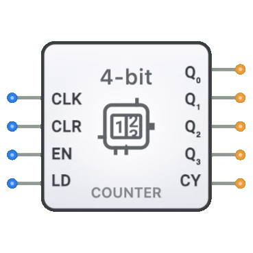
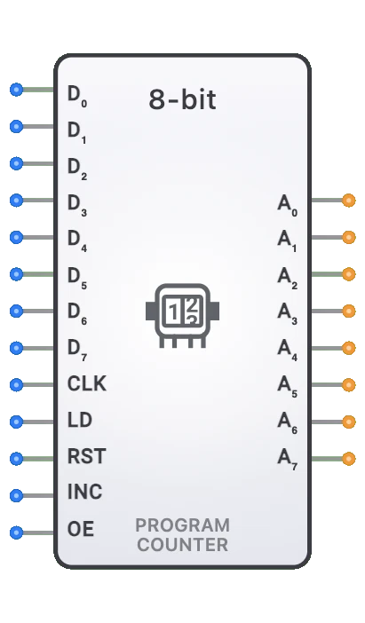
- シンボル: 8ビットカウンタは、クロック(CLK)、クリア(CLR)、イネーブル(EN)、ロード(LD)の入力と、現在のカウント値を表す8つのデータ出力およびキャリー出力を持つ矩形ブロックで表されます。
- DigiSim.ioでの役割: デジタルシステムにおけるタイミング、シーケンシング、カウント機能の実装に不可欠なコンポーネントとして機能し、より多くのカウント状態を必要とするアプリケーション向けに、小型カウンタよりも広い範囲(256状態)を提供します。

機能説明
論理動作
8ビットカウンタは、イネーブル時に各立ち上がりクロックエッジでバイナリシーケンスをインクリメントします。アップカウントのみです。クリアされると、クロックに関係なく非同期的にカウンタがゼロに戻��ます。
動作テーブル:
| CLR | EN | CLK | 動作 | 出力効果 |
|---|---|---|---|---|
| 1 | X | X | クリア(非同期) | Q = 0 |
| 0 | 1 | ↑ | カウントアップ | Q[n+1] = Q[n] + 1 |
| 0 | 0 | ↑ | 保持 | Q[n+1] = Q[n] |
| 0 | X | 0 | 変化なし | Q[n+1] = Q[n] |
注: ↑は立ち上がりクロックエッジ、Xは「ドントケア」条件を表します。カウンタは255から0にラップします。
入力と出力
入力:
- CLK(クロック): Pin 0。立ち上がりエッジでカウンタをトリガー。
- CLR(クリア): Pin 1。HIGHのときカウンタを非同期的に0にリセット。
- EN(イネーブル): Pin 2。HIGHのときカウントを有効化。
- LD(ロード): Pin 3。将来の使用のために予約(パラレルロードは現在サポートされていません)。
出力:
- Q[7:0]: 現在のカウント値を表す8ビット出力(Q0=LSB、Q7=MSB)。
- Carry: カウンタが最大値(255)に達したときHIGHになる1ビット出力。
設定可能なパラメータ
- クロックエッジ感度: カウンタが立ち上がりまたは立ち下がりクロックエッジに応答するかどうか。
- リセットタイプ: リセットが同期(クロックエッジでのみ)か非同期(即座)か。
- リセット値: カウンタがリセットされる値(通常ゼロ)。
- カウントシーケンス: カウンタがバイナリ、BCD、またはその他のカウントシーケンスに従うかどうか。
- 伝搬遅延: トリガーイベント後に出力が変化するまでの時間。
DigiSim.ioでの視覚的表現
8ビットカウンタは、左側にラベル付き入力(CLK、RST、EN、UP/DOWN)、右側に出力(Q[7:0]、COUT)を持つ矩形ブロックとして表示されます。クロック入力は通常、エッジ感度を示す三角形のシンボルで示されます。回路に接続すると、出力に表示されるバイナリ値と接続ワイヤの色の変化を通じて現在の状態を視覚的に示します。
教育的価値
主要概念
- 順序論理: デジタル回路が時間経過とともに状態を維持・更新する方法を実証します。
- バイナリカウント: バイナリ数シーケンスの進行を示します。
- 同期動作: クロック信号がデジタル操作をどのように調整・同期するかを示します。
- モジュラー算術: カウンタが範囲を超えたときのロールオーバー/ラップアラウンドの概念を提示します。
- 制御論理: イネーブルと方向制御を使用して回路動作を変更する方法を紹介します。
学習目標
- カウンタがバイナリシーケンスを通過し状態を維持する方法を理解する。
- リセット、イネーブル、方向などの制御信号がカウンタ動作にどのように影響するかを学ぶ。
- 同期と非同期カウンタ設計の違いを認識する。
- タイマー、シーケンサ、アドレス生成器の設計に8ビットカウンタを適用する。
- カウンタのオーバーフロー/アンダーフローの概念とキャリー出力がこれらの条件をどのように通知するかを理解する。
使用例/シナリオ
- アドレス生成: CPUまたはコントローラにおけるメモリ位置の順次アクセス。
- タイマー実装: 精密な時間遅延の作成または時間間隔の測定。
- イベントカウント: デジタルシステムにおけるイベントやパルスの発生回数の集計。
- 分周: プログラマブルファクタによる入力クロック周波数の分割。
- 状態シーケンシング: 有限状態機械のシーケンシング論理の実装。
- データ取得: アナログ信号サンプリングのタイミング制御。
- デジタル制御システム: 制御操作のタイミングシーケンスの生成。
技術ノート
- 8ビットカウンタは各種アーキテクチャで実装できます:
- 非同期(リプル)カウンタ: シンプルだがビット位置間の伝搬遅延問題がある。
- 同期カウンタ: 全フリップフロップが同時に変化し、より信頼性の高いタイミングを提供。
- 8ビットバイナリカウンタは、ロールオーバー前に0から255までの値を表現できます。
- 最大動作周波数はカウンタ論理の伝搬遅延によって制限されます。
- カウンタはキャリー出力を次のイネーブルに接続することで、より広いカウンタ(16ビット、32ビット)にカスケード接続できます。
- ジョンソンカウンタやリングカウンタなどの特殊カウンタ構成は、特定のアプリケーション向けに異なるカウントシーケンスを提供します。
- DigiSim.ioでは、カウンタの動作は制御入力の適切な処理と同期動作を備えた実際のデジタルコンポーネントをシミュレートします。
特性
入力構成:
- クロック入力(CLK): 状態遷移をトリガー、通常立ち上がりエッジでアクティブ
- リセット入力(RST): アサート時にカウンタを非同期的にゼロにリセット
- イネーブル入力(EN): カウント操作を有効化または無効化
- 方向制御(UP/DOWN): カウント方向を決定(ハイ時アップ、ロー時ダウン)
- 標準デジタル論理レベルと互換
- 一部の実装では追加入力(ロード、プリセットなど)を含む場合がある
- 典型的なクロック周波数範囲: 技術に応じてDCから50+ MHz
出力構成:
- 8つの状態出力(Q0-Q7)
- キャリー/ボロー出力(Cout) - カウンタがオーバーフロー(アップ)またはアンダーフロー(ダウン)時にアサート
- 各出力は現在のカウント値の1ビットを表す
- Q0が最下位ビット(LSB)、Q7が最上位ビット(MSB)
- 標準デジタル負荷を駆動可能
- 一部の実装では相補出力を含む場合がある
機能:
- 0から255(または255から0)のバイナリシーケンスでカウント
- 完全な8ビット範囲で256の異なる状態を提供
- アップカウント時は255から0にラップアラウンド
- ダウンカウント時は0から255にラップアラウンド
- ラップアラウンド条件でキャリー出力を生成
- 異なるカウントシーケンスに設定可能
- 追加論理によるモジュロNカウントが可能
伝搬遅延:
- クロックから出力: 通常15-35ns
- セットアップ時間: クロックエッジ前10-20ns
- ホールド時間: クロックエッジ後0-10ns
- リセットから出力: 10-25ns
- 技術依存(TTL、CMOSなど)
- 同期設計では一貫した出力タイミング
- カスケード非同期実装ではより高い遅延
ファンアウト:
- 通常10-20の標準負荷を駆動
- 出力負荷が伝搬遅延に影響
- 高ファンアウトアプリケーションではバッファリングが必要な場合がある
- 現代のCMOS実装は改善された駆動能力を持つ
消費電力:
- CMOS実装では静的電力が最小
- クロック周波数に伴い動的電力が増加
- 状態が変化するビット数に比例
- 追加フリップフロップにより4ビットカウンタより高い
- 多くの実装で電力管理機能
- 高速アプリケーションでは顕著な場合がある
回路複雑度:
- 中程度から高い複雑度
- 8つのフリップフロップと制御論理が必要
- 同期設計は非同期より複雑
- パラレルロードなどの機能のための追加論理
- 機能セットに伴い複雑度が増加
- 統合バージョンにより外部コンポーネント数を削減
実装方法
非同期(リプル)カウンタ
- 8つのフリップフロップ(通常TまたはJKタイプ)のカスケード
- 各フリップフロップ出力が次のクロックを駆動
- シンプルな実装だが伝搬遅延問題がある
- LSBは毎クロック変化、上位ビットは駆動時に変化
- 高速アプリケーションには不適
- 遷移中にグリッチが発生する可能性がある
- 最もシンプルな設計だがタイミングに制限
同期カウンタ
- 全フリップフロップが共通クロックを共有
- 状態遷移が同時に発生
- どのフリップフロップがトグルするかを決定する追加の組合せ論理
- リプル設計よりも複雑だがタイミングが改善
- 非同期設計より高速動作
- 予測可能なタイミング動作
- D、JK、またはTフリップフロップで実装可能
アップ/ダウンバイナリカウンタ
- 双方向カウント機能
- 各フリップフロップ用の方向制御論理
- 方向制御のための追加複雑度
- アプリケーション固有のカウンタで一般的
- 信頼性の高い動作のために同期実装が好ましい
- 両方向のキャリー/ボロー論理
プリセッタブルカウンタ
- パラレルロード機能を含む
- 各ビットのデータ入力
- ロードイネーブル制御信号
- 任意の値に初期化可能
- 特定間隔のタイミングに有用
- ロードパスのための追加マルチプレクサ
- プログラマブルタイマーアプリケーションで一般的
BCD(二進化十進)カウンタ
- 2つのBCD桁を持つ修正8ビットカウンタ
- 10進で0から99までカウント
- 各4ビットセクションのカウント10でのリセット論理
- 人間が読めるカウントアプリケーションに有用
- ディスプレイとユーザーインターフェースで一般的
- より複雑なデコーディング論理
集積回路実装
- 専用カウンタICとして利用可能
- 74xxシリーズで一般的(74LS590、74HC590、カスケードした74HC393)
- 各種機能: プリセット可能、カスケード可能、アップ/ダウン
- 各種速度/電力要件に対応する異なる技術
- トライステート出力などの追加機能を含む場合がある
- システム設計でのコンポーネント数の削減
FPGA/ASIC実装
- フリップフロップとLUTを使用した効率的な実装
- 高度に設定可能で最適化可能
- 特殊機能を容易に追加可能
- HDL記述から合成されることが多い
- 現代のプログラマブルロジックでリソース効率が高い
- 特定のタイミング要件に合わせた調整可能
アプリケーション
メモリアドレッシング
- マイクロコントローラおよびCPUのプログラムカウンタ
- 順次メモリアクセス用のアドレス生成
- DRAMリフレッシュカウンタ
- コンピューティングシステムのスタックポインタ
- メモリ転送用DMAコントローラ
- メモリ位置の順次走査
タイミング生成
- 精密なタイミング間隔(最大256クロックサイクル)
- プログラマブル遅延生成
- パルス幅制御
- システムタイミング調整
- リアルタイムクロックサブシステム
- タイムアウト生成
分周
- 最大256の分割比を持つクロック分周器
- 精密周波数合成
- 信号生成器
- 通信用ボーレート生成器
- デジタルシステムのクロック管理
- 周波数スケーリング
イベントカウント
- 広範囲のイベント集計
- 計測におけるパルスカウント
- 回転数カウント
- フロー測定
- 発生率モニタリング
- 生産ラインカウント
デジタル制御システム
- ステートマシンの実装
- 制御操作のシーケンシング
- モーター制御タイミング
- プロセスコントローラ
- 産業用オートメーションシーケンシング
- 時間ベースの制御アルゴリズム
データ取得
- サンプルタイミング制御
- ADC制御シーケンシング
- データバッファリングアドレス
- 測定トリガー生成
- サンプリングレート制御
- ノイズ低減用平均化カウンタ
通信システム
- データパケットのフレームカウンタ
- シリアルプロトコルのバイトシーケンシング
- 通信タイミング
- プロトコルシーケンシング
- エラー検出カウンタ
- ビットタイミング生成器
制限事項
タイミング制約
- 技術によって制限される最大動作周波数
- 信頼性の高い動作のためのセットアップ時間とホールド時間の要件
- 複雑なシステムでのクロックスキューの懸念
- 非同期設計での伝搬遅延の蓄積
- リセット回復タイミング要件
- リプル実装での全ビットにわたる不一致なタイミング
グリッチとレースコンディション
- 遷移中の出力グリッチ(特に非同期設計で)
- マルチビット遷移中の中間状態
- 制御アプリケーションでは重要
- 下流論理の誤トリガーの可能性
- 出力デコード論理でのハザード
- カウンタフィードバックパスでのレースコンディション
範囲制限
- 8ビット値(0-255)に制限
- より大きなカウント範囲にはカスケードが必要
- 範囲を超えるカウントのオーバーフロー処理
- 非バイナリシーケンスには追加論理が必要
- モジュロNカウントには追加論理が必要
- 小さなカウント範囲には非効率
消費電力
- 高速クロックレートでの高い動的電力
- 複数ビット遷移中の電力スパイク
- バッテリー駆動アプリケーションでは顕著
- スイッチング周波数に伴い増加
- フリップフロップが多いため小型カウンタより高い
- 高速動作での熱的考慮
設計複雑度
- 小型カウンタよりも複雑
- 高度な機能により論理要件が増加
- 同期設計にはより多くの組合せ論理が必要
- テストおよび検証の複雑度
- コンポーネント数または論理リソースの増加
- 重要なアプリケーションでの複雑なタイミング分析
回路実装の詳細
8ビット同期バイナリアップカウンタ
graph TB
    Clock[Clock CLK] --> FlipFlop0[Flip-Flop 0]
    Clock --> FlipFlop1[Flip-Flop 1]
    Clock --> FlipFlop2[Flip-Flop 2]
    Clock --> DOTS[...]
    Clock --> FlipFlop7[Flip-Flop 7]

    Reset[Reset RST] --> FlipFlop0
    Reset --> FlipFlop1
    Reset --> FlipFlop2
    Reset --> DOTS
    Reset --> FlipFlop7

    FlipFlop0 --> OutputQ0[Q0]
    FlipFlop1 --> OutputQ1[Q1]
    FlipFlop2 --> OutputQ2[Q2]
    DOTS --> QDOTS[...]
    FlipFlop7 --> OutputQ7[Q7]

    ControlLogic[Enable & Clock<br/>Control Logic]
    Enable[Enable EN] --> ControlLogic
    UpDown[UP/DOWN] --> ControlLogic
    ControlLogic -.-> FlipFlop0
    ControlLogic -.-> FlipFlop1
    ControlLogic -.-> FlipFlop2
    ControlLogic -.-> FlipFlop7
74HC590 出力レジスタ付き8ビットバイナリカウンタ
    ┌─────────────────┐
    │                 │
    │     74HC590     │
    │                 │
CLK ┤CP            Q0 ├── Q0
    │                 │
MR  ┤MR            Q1 ├── Q1
    │                 │
    │               Q2 ├── Q2
    │                 │
    │               Q3 ├── Q3
    │                 │
    │               Q4 ├── Q4
    │                 │
    │               Q5 ├── Q5
    │                 │
    │               Q6 ├── Q6
    │                 │
    │               Q7 ├── Q7
    │                 │
CEP ┤CEP              │
    │                 │
CET ┤CET          Q7S ├── Cout
    │                 │
OE  ┤OE               │
    │                 │
RCK ┤RCK              │
    │                 │
    └─────────────────┘
CP = クロックパルス入力、MR = マスターリセット、CEP/CET = カウントイネーブル入力、 OE = 出力イネーブル、RCK = レジスタクロック、Q7S = キャリー出力
関連コンポーネント
- 4ビットカウンタ: 0-15の範囲を持つ小型カウンタ
- 16ビットカウンタ: 0-65535の範囲を持つ拡張カウンタ
- BCDカウンタ: 10進桁シーケンスでカウント
- アップ/ダウンカウンタ: 方向制御付き双方向カウンタ
- ロード可能カウンタ: パラレルデータロード機能を持つカウンタ
- ジョンソンカウンタ: 状態あたり1ビット変化の反転フィードバック付きシフトレジスタ
- リングカウンタ: 単一ビットを循環させる直接フィードバック付きシフトレジスタ
- カスケードカウンタ: カウント範囲を拡大するために接続された複数のカウンタ
- 分周器: クロック分割に特化して使用されるカウンタ
- プログラムカウンタ: プロセッサにおける命令シーケンシング用の特殊カウンタ