マルチプレクサ
概要
- 目的: マルチプレクサ(MUX)は、複数の入力信号の中から1つを選択し、単一の出力ラインに転送するデジタルコンポーネントです。複数の入力データラインの1つを出力にルーティングする、デジタル制御のスイッチとして機能します。
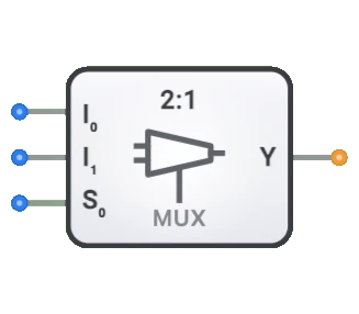
- シンボル: マルチプレクサは、2つのデータ入力(D0、D1)、選択入力(Sel)、および単一の出力(Y)を持つ長方形のブロックで表されます。
- DigiSim.ioでの役割: DigiSim.ioのマルチプレクサは、単一の選択ラインに基づいて2つのデータ入力から選択する2対1(2:1)MUXであり、デジタル回路における基本的なデータ選択コンポーネントとして機能します。
機能説明
論理動作
DigiSim.ioのマルチプレクサは2対1 MUXです。単一の選択入力(Sel)を使用して、2つのデータ入力(D0またはD1)のどちらを出力(Y)に転送するかを決定します。Sel=0の場合、出力YはD0に等しくなります。Sel=1の場合、出力YはD1に等しくなります。
真理値表(2対1マルチプレクサ):
| Sel | D0 | D1 | Y |
|---|---|---|---|
| 0 | 0 | X | 0 |
| 0 | 1 | X | 1 |
| 1 | X | 0 | 0 |
| 1 | X | 1 | 1 |
入力と出力
入力(合計3):
- D0(データ0): Sel=0の場合に選択される1ビットデータ入力。
- D1(データ1): Sel=1の場合に選択される1ビットデータ入力。
- Sel(選択): どのデータ入力(D0またはD1)が出力に表示されるかを決定する1ビット制御入力。
出力(合計1):
- Y(出力): 選択されたデータ入力の値を反映する1ビット出力。
設定可能なパラメータ
- 伝搬遅延: 選択または入力変化後に出力が変化するまでの時間。
DigiSim.ioでの視覚的表現
マルチプレクサは、片側に2つのデータ入力(D0、D1)、通常は下部に選択入力(Sel)を持つ長方形のブロックとして表示されます。出力(Y)は反対側にあります。回路に接続すると、接続ワイヤの色の変化を通じてアクティブなデータパスと論理状態を視覚的に示します。
教育的価値
主要概念
- データ選択: 複数のオプションから1つの信号を選択する概念を実証します。
- デジタルスイッチング: デジタルシステムがどのようにデータを動的にルーティングするかを説明します。
- バイナリエンコーディング: バイナリの選択値が特定のデータパスにどのように対応するかを示します。
- 組み合わせ論理: マルチプレクサを使用して複雑な論理関数をどのように実装できるかを紹介します。
学習目標
- マルチプレクサがデジタルシステムにおいてどのようにデータの流れを制御するかを理解する。
- バイナリ選択コードがどの入力が出力にルーティングされるかをどのように決定するかを学ぶ。
- より大きなデジタルシステムの作成におけるマルチプレクサの役割を認識する。
- さまざまな組み合わせ論理関数を実装するためにマルチプレクサを適用する。
- マルチプレクサが特定の回路設計でコンポーネント数をどのように削減できるかを理解する。
使用例/シナリオ
- データ選択: 処理対象の複数のデータソースの1つを選択する。
- バスシステム: どのデバイスが共有データバスにアクセスするかを制御する。
- 論理実装: 定数や変数を入力として使用してマルチプレクサで任意の組み合わせ論理関数を実装する。
- パラレル-シリアル変換: パラレル入力から順次ビットを選択する。
- メモリシステム: 特定のメモリセルまたはワードのアドレッシングと選択。
技術ノート
- 選択ライン数(S)とデータ入力数(I)には関係があります:2^S = I。例えば、DigiSim.ioの2対1マルチプレクサは、2つのデータ入力から選択するために1本の選択ラインを使用します。
- 複数のマルチプレクサをカスケード接続することで、より大きなマルチプレクサを作成できます。例えば、2つの4:1マルチプレクサと1つの2:1マルチプレクサで8:1マルチプレクサを作成できます。
- マルチプレクサをデマルチプレクサと組み合わせて、双方向データルーティングシステムを作成できます。
- 物理的な実装では、選択ライン遷移中にマルチプレクサが短い出力グリッチを経験する場合があります。
特性
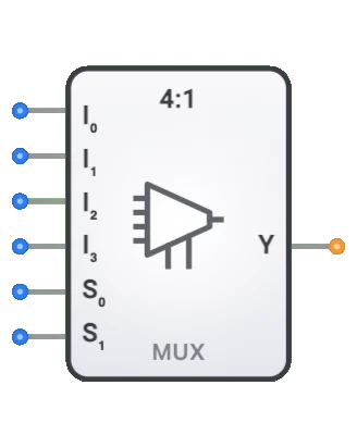
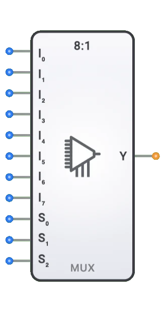
- チャネル数: N:1として記述(例:2:1、4:1、8:1、16:1)
- 選択ライン: N個のデータ入力から選択するためのlog₂(N)の選択入力
- 伝搬遅延: 入力変化と安定した出力の間の時間
- ファンアウト: 駆動できる論理ゲートの数
- 消費電力: 通常チャネル数に伴い増加
- イネーブル制御: 一部のマルチプレクサにはイネーブル入力が含まれる
- データ幅: 1ビットまたはマルチビット(バスマルチプレクサ)
- グリッチ耐性: 遷移中の一時的な不正出力を回避する品質
マルチプレクサの種類
バイナリマルチプレクサ
- 2:1(1本の選択ライン)
- 4:1(2本の選択ライン)
- 8:1(3本の選択ライン)
- 16:1(4本の選択ライン)
バスマルチプレクサ
- 複数のビットをパラレルで処理
- 一般的な幅:4ビット、8ビット、16ビット、32ビット
アナログマルチプレクサ
- アナログ信号を切り替え
- オン時の低抵抗で信号の完全性を維持
ツリーマルチプレクサ
- より小さなマルチプレクサをカスケードして構築
- 大規模な実装に使用
双方向マルチプレクサ
- いずれの方向にも信号フローが可能
- 双方向バスで使用
アプリケーション
データ選択とルーティング
- 複数のデータソースから選択
- DRAMにおけるメモリアドレスマルチプレクシング
- コンピュータシステムにおけるバスアービトレーション
通信システム
- チャネル共有のための時分割多重化(TDM)
- 通信におけるライン選択
- ネットワークスイッチングアプリケーション
論理実装
- ブール関数の実装
- FPGAにおけるルックアップテーブル(LUT)
- プログラマブルロジックアレイ
テストとデバッグ
- 信号のプロービングと監視
- テストポイントの選択
- 診断信号ルーティング
算術回路
- ALU機能の選択
- 条件付き演算
- ビット操作関数
制御システム
- 動作モードの選択
- 信号パスの構成
- ステートマシンの実装
実装
マルチプレクサは以下を使用して実装できます:
基本論理ゲート
- AND、OR、NOTゲート
- トランスミッションゲート
集積回路
- 74xxシリーズ:
- 74157:クワッド2:1マルチプレクサ
- 74153:デュアル4:1マルチプレクサ
- 74151:8:1マルチプレクサ
- 74150:16:1マルチプレクサ
- 74xxシリーズ:
トランジスタレベル
- CMOSパストランジスタ
- トランスミッションゲート
- トライステートバッファ
HDL設計(Verilog/VHDL)
- Case文
- 条件付き代入
- パラメータ化された設計
回路実装(2:1 MUX)
基本的な2:1マルチプレクサは基本論理ゲートを使用して実装できます:
AND-ORゲート実装
graph LR
    Input0[Input I0] --> AndGate0[AND Gate]
    SelectS[Select S] --> NotGate[NOT Gate]
    NotGate --> AndGate0

    Input1[Input I1] --> AndGate1[AND Gate]
    SelectS --> AndGate1

    AndGate0 --> OrGate[OR Gate]
    AndGate1 --> OrGate
    OrGate --> OutputY[Output]
トランスミッションゲート実装
graph LR
    Input0[Input I0] --> TransGate0[Transmission Gate 0]
    Input1[Input I1] --> TransGate1[Transmission Gate 1]

    TransGate0 --> OutputY[Output]
    TransGate1 --> OutputY

    SelectS[Select S] --> TransGate1
    SelectS --> NotGate[NOT Gate]
    NotGate --> TransGate0
関連コンポーネント
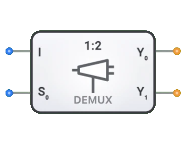
- デマルチプレクサ: 逆の操作を実行(1対Nルーティング)
- エンコーダ: 複数の入力ラインをバイナリコードに変換
- デコーダ: バイナリコードを複数の出力ラインに変換
- バストランシーバ: 方向制御付き双方向データ転送
- セレクタ: マルチプレクサに似ていますが異なる制御ロジック
- クロスバースイッチ: 柔軟な相互接続のためのマルチプレクサのグリッド
- プライオリティエンコーダ: 最高優先度の入力を選択
- デジタルスイッチ: 機械式スイッチの電子的等価物
- マルチプレクサツリー: 大きな入力数のためのカスケードマルチプレクサ
- プログラマブルロジックアレイ: マルチプレクサを構成要素として使用