フラグレジスタ
概要
- 用途: フラグレジスタは、算術演算や論理演算の結果を反映するステータスビット(フラグ)を格納する特殊用途レジスタです。各ビットは、結果がゼロであったか、負であったか、キャリーが発生したか、オーバーフローが発生したかなど、特定の条件に対応しています。
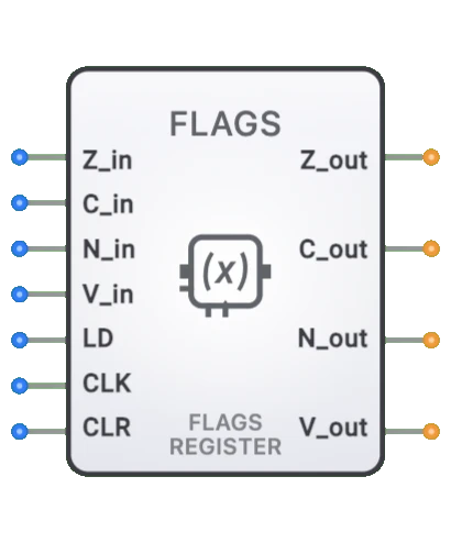
- シンボル: 7つの入力(4つのフラグデータバス入力 + CLK + LD + フラグ入力)と4つのフラグ出力(Z、C、N、V)を持つ矩形レジスタブロックとして表現されます。
- DigiSim.ioでの役割: コンピュータアーキテクチャシミュレーションにおける重要なコンポーネントとして機能し、前回の計算結果に基づく条件付き動作と意思決定を可能にします。
機能説明
論理動作
フラグレジスタは、ALUや他の演算ユニットによって生成されたステータス情報をキャプチャして格納します。レジスタの各ビットは特定の条件または状態を表します。
フラグ:
| フラグ | セット条件 | クリア条件 |
|---|---|---|
| ゼロ (Z) | 演算結果がゼロ | 結果が非ゼロ |
| キャリー (C) | 符号なし加算オーバーフロー / 減算ボロー | 符号なしオーバーフローなし / ボローなし |
| 負 (N) | 結果の最上位ビット(MSB)が1 | 結果のMSBが0 |
| オーバーフロー (V) | 符号付き算術演算がオーバーフロー | 符号付きオーバーフローなし |
入力と出力
入力(合計7):
- Zero (Z): ピン0。ALUからのゼロフラグ入力(バス入力)。
- Carry (C): ピン1。ALUからのキャリーフラグ入力(バス入力)。
- Negative (N): ピン2。ALUからの負フラグ入力(バス入力)。
- Overflow (V): ピン3。ALUからのオーバーフローフラグ入力(バス入力)。
- Flag In: ピン4。追加フラグ入力(バス入力)。
- CLK: ピン5。クロック入力 — 立ち上がりエッジでフラグがキャプチャされます。
- LD (Load): ピン6。ロードイネーブル — 立ち上がりクロックエッジでLDがHIGHの場合のみフラグが更新されます。
出力(合計4):
- Z: ピン0。ゼロフラグ出力。
- C: ピン1。キャリーフラグ出力。
- N: ピン2。負フラグ出力。
- V: ピン3。オーバーフローフラグ出力。
設定可能なパラメータ
- 含まれるフラグ: 実装される特定のステータスフラグ(アーキテクチャに依存)。
- フラグ動作: 各フラグが特定の演算に対してどのように応答するか。
- クロックエッジ感度: レジスタが立ち上がりまたは立ち下がりクロックエッジで更新されるかどうか。
- ロード制御: フラグが個別にまたはグループとして更新されるかどうか。
- 伝搬遅延: フラグ出力が入力変化を反映するまでの時間。
DigiSim.ioでの視覚的表現
フラグレジスタは、左側にラベル付き入力(ステータスビット、CLK、Load)、右側に個別のフラグ出力(Z、C、N、Vなど)を持つ矩形ブロックとして表示されます。回路に接続すると、コンポーネントは出力値と接続ワイヤの色変化を通じて各フラグの状態を視覚的に示します。
教育的価値
主要概念
- 条件付き実行: コンピュータが演算結果に基づいてどのように判断を行うかを実演します。
- ステータス追跡: デジタルシステムが計算結果をどのように追跡するかを示します。
- コンピュータアーキテクチャ: CPU設計の基本コンポーネントを説明します。
- 状態情報: 後続の演算で使用するための状態情報を維持する概念を紹介します。
- デジタルフィードバック: 演算結果が将来の処理パスにどのように影響するかを示します。
学習目標
- ステータスフラグが算術演算および論理演算の結果をどのようにキャプチャするかを理解する。
- フラグがコンピュータプログラムにおける条件分岐と意思決定をどのように可能にするかを学ぶ。
- CPUアーキテクチャと命令実行におけるフラグレジスタの役割を認識する。
- フラグの知識を条件付き演算におけるプログラムフローの予測に適用する。
- 多倍精度演算がキャリーフラグとオーバーフローフラグにどのように依存するかを理解する。
使用例/シナリオ
- 条件分岐: ゼロならジャンプ(JZ)、キャリーならジャンプ(JC)、非ゼロならジャンプ(JNZ)命令がフラグを使用してプログラムフローを変更します。
- 多倍精度演算: キャリーフラグを使用して複数ワードにわたる演算をリンクします(例:32ビットALUで64ビット数を加算)。
- エラー検出: オーバーフローフラグを監視して符号付き演算の算術エラーを検出します。
- ループ制御: ゼロフラグをチェックしてループカウンタが終了値に達したかを判定します。
- 割り込み管理: 割り込みフラグをセットまたはクリアして、外部イベントに対するシステムの応答性を制御します。
- ステータスレポート: フラグを使用して演算結果を上位レベルのソフトウェアに伝達します。
技術ノート
- フラグレジスタは通常、各フラグビットに1つのフリップフロップを持つコレクションとして実装されます。
- CPUアーキテクチャによって含まれるフラグのセットや解釈が異なる場合があります。
- フラグの動作は命令によって異なる場合があり、すべてのフラグに影響する命令もあれば、特定のフラグのみに影響する命令もあります。
- 多くのCPU設計では、フラグレジスタはより大きなプログラムステータスワード(PSW)またはステータスレジスタの一部です。
- コンテキストスイッチ、割り込み、サブルーチンコール時にはフラグレジスタの保存と復元が必要になることがよくあります。
- DigiSim.ioでは、フラグレジスタの動作は入力条件に基づく適切なフラグのセットとクリアにより、一般的なCPUアーキテクチャをモデル化しています。