Your First Circuits in DigiSim.io: A Beginner's Guide
Build three starter circuits in DigiSim.io: a switch-and-light, an AND gate, and a multi-gate alarm. No installs, no prerequisites — only a browser needed.

TL;DR: This tutorial walks through three starter circuits in DigiSim.io: a switch-driven light (digital signals), a 2-input AND gate (logic gates and truth tables), and a multi-gate alarm system (combining gates into useful behavior). Each circuit takes only a few minutes and requires nothing but a browser.
Never touched digital logic before? This tutorial takes you from zero to three working circuits, each teaching a fundamental concept. No prior experience needed — only a web browser and curiosity.
By the end, you will have built a direct connection circuit, a logic gate circuit, and a simple alarm system. More importantly, you will understand the core ideas behind each one: digital signals, logical decision-making, and combining gates to produce useful behavior.
Project 1: The Switch-to-Light Circuit (Your “Hello World”)
Every digital circuit has the same basic structure: an input generates a signal, wires carry the signal, and an output responds to it. We will build the simplest possible version of this structure.
Step-by-Step
Step 1 — Open DigiSim.io
Go to digisim.io/circuits/new in your browser. You will see a blank canvas with a component palette on the left. This canvas is where you build circuits by placing components and connecting them with wires.
Step 2 — Place a Switch
In the component palette, find Switch under Input components. Click it, then click on the canvas to place it on the left side. This switch is your input device. It has two states: OFF (sends a 0 signal) and ON (sends a 1 signal).
Step 3 — Place a Light
Find Light under Output components. Click to select it, then click on the canvas to the right of your switch. The light is your output device. It responds to the signal it receives: 0 means dark, 1 means glowing.
Step 4 — Connect Them
Hover over the small circle on the right side of the switch (its output port). Click and drag to the small circle on the left side of the light (its input port). A wire appears connecting the two components.
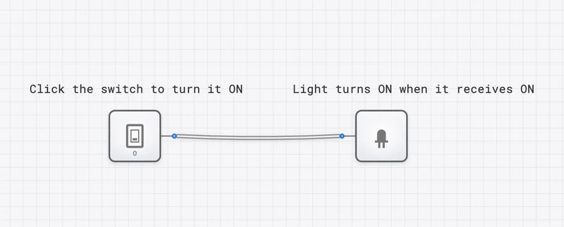
Step 5 — Test It
Click the switch to toggle it. The light turns ON. Click again. The light turns OFF. You have a working digital circuit.
What You Learned
- Digital signals have two states: 0 (OFF/LOW) and 1 (ON/HIGH). There is no in-between. This binary nature is the foundation of all digital electronics.
- Wires carry signals from one component to another without changing them.
- Inputs generate signals, outputs respond to them. This input-processing-output structure appears in every digital system, from a simple switch circuit to a multi-billion-transistor processor.
This is genuinely how all digital electronics work at the lowest level. Your phone’s touchscreen generates digital signals (input), the processor manipulates them (processing), and the display responds (output). The complexity differs, but the principle is identical.
Project 2: The AND Gate Circuit (Making Decisions)
A direct wire connection is not very interesting — the output just copies the input. The power of digital logic comes from placing logic gates between inputs and outputs. A gate examines its inputs and produces an output based on a specific rule.
The AND gate follows this rule: the output is 1 only when all inputs are 1. If any input is 0, the output is 0.
Step-by-Step
Step 1 — Start Fresh
Open a new circuit at digisim.io/circuits/new, or clear your existing canvas.
Step 2 — Place Two Switches
Drag two Switch components onto the left side of the canvas, one above the other. These will be your two inputs, A and B.
Step 3 — Place an AND Gate
Find AND under Logic Gates in the palette. Place it in the center of the canvas, between the switches and where your output will go. The AND gate has two input ports on the left and one output port on the right.
Step 4 — Place a Light
Place an Output Light to the right of the AND gate.
Step 5 — Wire the Circuit
- Connect the top switch’s output to the AND gate’s top input.
- Connect the bottom switch’s output to the AND gate’s bottom input.
- Connect the AND gate’s output to the light’s input.
Step 6 — Test All Four Combinations
Systematically toggle the switches through every possible combination and record what happens:
| Switch A | Switch B | Light | Why |
|---|---|---|---|
| OFF (0) | OFF (0) | OFF | Neither condition met |
| OFF (0) | ON (1) | OFF | Only one condition met |
| ON (1) | OFF (0) | OFF | Only one condition met |
| ON (1) | ON (1) | ON | Both conditions met |
The light turns on only when both switches are on. This is the AND rule.
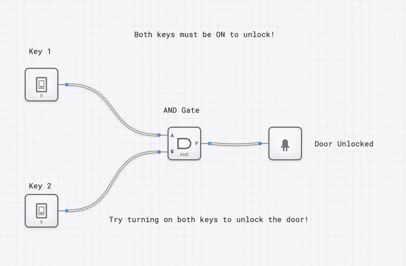
An AND gate in action: both switches must be ON for the light to illuminate — like a two-key security system.
What You Learned
- Logic gates make decisions. The AND gate does not just pass a signal through; it evaluates its inputs and produces an output based on a logical rule.
- The AND rule requires unanimity. Every input must be 1 for the output to be 1. This is why AND gates are used in safety systems (a machine that requires two buttons pressed simultaneously) and security systems (a vault that requires two keys turned at once).
- Four input combinations for two inputs. With two binary inputs, there are exactly possible combinations. You just tested all of them. This exhaustive testing — checking every possible input — is how engineers verify that a circuit is correct.
Project 3: A Simple Alarm System (Combining Concepts)
Now we combine what you have learned into a circuit with a practical purpose: a simple alarm system. The alarm should trigger (light turns on) if a door sensor OR a window sensor detects an intrusion, but only when the alarm system is enabled (armed).
The logic: (Door OR Window) AND Armed = Alarm
This requires two gates: an OR gate to combine the two sensors, and an AND gate to check whether the system is armed.
Step-by-Step
Step 1 — Plan the Circuit
Before placing components, think about the signal flow:
- Three inputs: Door sensor, Window sensor, Armed switch.
- An OR gate combines the two sensors (“is either sensor triggered?”).
- An AND gate checks whether the OR output AND the Armed switch are both 1 (“is there an intrusion AND is the system armed?”).
- One output: the Alarm light.
Step 2 — Place the Components
Open a new circuit. Place three Switches on the left (label them Door, Window, Armed if you like). Place an OR gate and an AND gate in the middle. Place an Output Light on the right.
Step 3 — Wire the Circuit
- Connect the Door switch to one input of the OR gate.
- Connect the Window switch to the other input of the OR gate.
- Connect the OR gate’s output to one input of the AND gate.
- Connect the Armed switch to the other input of the AND gate.
- Connect the AND gate’s output to the light.
Step 4 — Test the Alarm Logic
Work through the important test cases:
Test 1: System disarmed (Armed = 0). Toggle Door and Window freely. The alarm should never trigger, because the AND gate blocks the signal when Armed is 0.
Test 2: System armed, no intrusion (Armed = 1, Door = 0, Window = 0). The OR gate outputs 0 (no sensor triggered), so the AND gate outputs 0. Alarm stays off. Correct.
Test 3: System armed, door opened (Armed = 1, Door = 1, Window = 0). The OR gate outputs 1 (at least one sensor triggered), the AND gate sees 1 AND 1, so the alarm triggers. Correct.
Test 4: System armed, window opened (Armed = 1, Door = 0, Window = 1). Same as Test 3 but through the window sensor. The OR gate still outputs 1, the alarm triggers. Correct.
Test 5: System armed, both sensors triggered (Armed = 1, Door = 1, Window = 1). The OR gate outputs 1, the AND gate outputs 1. Alarm triggers. Correct.
What You Learned
- Gates combine to create complex behavior. The OR gate asks “is anything wrong?” The AND gate asks “should we care right now?” Together, they implement a useful security policy.
- Boolean expressions describe circuits. The alarm’s behavior is captured in one expression: . This is the same equation you built with physical gates.
- Signal flow is sequential. The Door and Window signals pass through the OR gate first, then the OR output passes through the AND gate. The order of operations matters and follows the wiring.
- Real systems use this exact pattern. Actual alarm panels use OR gates (or their equivalent) to combine zone sensors and AND gates to implement arming/disarming logic. You just built a simplified version of a genuine security system.
Understanding What You Built: The Big Picture
Across these three projects, you encountered the fundamental concepts of digital logic:
| Concept | Where You Saw It |
|---|---|
| Digital signals (0 and 1) | Every switch toggle |
| Wires carry signals | Every connection you drew |
| Logic gates make decisions | AND gate, OR gate |
| Truth tables map all possibilities | Testing all switch combinations |
| Boolean expressions describe logic | , |
| Combining gates builds complex behavior | The alarm system |
These same concepts, applied at massive scale, produce everything from pocket calculators to server farms. The gap between your alarm circuit and a modern processor is one of scale, not of kind. A processor is millions of gates wired together, but each individual gate follows the exact same rules you just tested.
What to Explore Next
You now have the foundation. Here are four directions to grow:
Try the NOT Gate
Place a NOT gate between a switch and a light. The output is always the opposite of the input. Then try placing a NOT gate after an AND gate — you have just built a NAND gate, which is the most important gate in chip manufacturing because any other gate can be built from NAND gates alone.
Modify the Alarm System
Add a third sensor (e.g., a motion detector) to the OR gate’s inputs. The alarm now triggers if any of three sensors detects an intrusion. Observe how the OR gate naturally scales to handle additional inputs.
Try a Template
DigiSim.io includes pre-built circuit templates that demonstrate more advanced concepts. Open one, trace the signal flow, and experiment with the inputs to understand the behavior before you try building something similar from scratch.
Follow the Structured Lessons
The SimCast interactive lessons provide a guided path from basic gates through combinational circuits, sequential logic, and processor design. Each lesson builds on the previous one and includes embedded simulations.
Quick Reference
| Component | Type | What It Does |
|---|---|---|
| Switch | Input | Generates a 0 or 1 signal |
| Light | Output | Glows when receiving a 1 |
| AND Gate | Logic | Output is 1 only when ALL inputs are 1 |
| OR Gate | Logic | Output is 1 when ANY input is 1 |
| NOT Gate | Logic | Inverts the input (0 becomes 1, 1 becomes 0) |
| Wire | Connection | Carries a signal from one component to another |
When you are ready, the natural next stop is Digital Logic 101 for a deeper look at AND, OR, and NOT, then Logic Gate Truth Tables as a single-page reference covering every gate.