Grading Circuits in Seconds: The DigiSim Workflow
Cut circuit-lab grading time by 80% with DigiSim.io shareable URLs. Test student submissions functionally, apply rubrics, and give feedback fast.

TL;DR: Shareable DigiSim.io URLs replace breadboard photos and screenshots with circuits that the grader can actually run. Functional testing — toggling each input combination — takes seconds per submission, and a four-criterion rubric (correctness, efficiency, clarity, submission quality) keeps grading consistent.
Grading digital logic lab assignments has historically been one of the most time-consuming tasks in teaching. Physical breadboard submissions require live demonstrations or blurry photographs, and even well-organized screenshot submissions leave the grader unable to test whether the circuit actually works. This guide presents a complete assessment workflow for digital logic courses using shareable circuit URLs, covering rubric design principles, formative and summative assessment strategies, common student misconceptions to check for, and concrete examples at multiple complexity levels.
The Traditional Grading Problem
With physical labs or screenshot-based submissions, instructors face several compounding problems:
- Untestable submissions. A photograph of a breadboard cannot be run. The grader must mentally trace wires and infer behavior, a process that is slow and error-prone.
- Inconsistent evaluation. Fatigue sets in after the 20th submission. Standards drift. What earns full marks at 2 PM gets a deduction at 10 PM.
- No partial credit granularity. When you cannot test a circuit, it is difficult to determine which input combinations produce correct output and which do not.
- Plagiarism is hard to detect. Two identical breadboard photos look different because of wire colors and layout. Two identical simulated circuits can be compared structurally.
- Time cost. Each breadboard submission takes 5-15 minutes to evaluate. With 50 students submitting 10 assignments, that is 40+ hours of grading per semester.
The shareable URL model eliminates most of these problems. Students build circuits in DigiSim.io, generate a shareable link, and submit it through the LMS. The instructor clicks the link, the circuit opens in the browser exactly as the student built it, and functional testing takes seconds.
The DigiSim Grading Workflow
Step 1: Student Builds and Shares
Students build their circuit in DigiSim.io. When finished, they generate a shareable URL and submit it through the LMS (Canvas, Blackboard, Moodle, Google Classroom, etc.).
Step 2: Click and Open
The instructor clicks the submitted URL. The circuit opens instantly in the browser, exactly as the student left it. No file downloads, no software installation, no compatibility issues.
Step 3: Functional Testing
The instructor toggles input switches through predetermined test cases, observing whether the outputs match the expected truth table. For combinational circuits, this is exhaustive (all input combinations). For sequential circuits, it follows a predefined test sequence.
Step 4: Assessment and Feedback
The instructor records the grade based on a rubric (detailed below) and enters feedback in the LMS. Total time per submission: 1-3 minutes for basic gates, 3-5 minutes for complex combinational circuits.
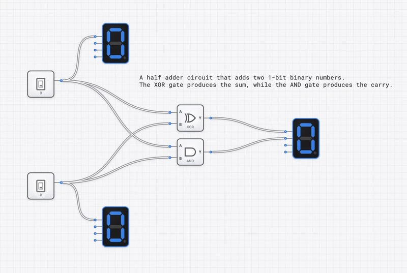
A student’s Half Adder submission: instant visual verification of all four input combinations in under 30 seconds.
Rubric Design Principles
A well-designed rubric serves two purposes: it makes grading consistent and efficient, and it communicates to students exactly what is expected. For circuit lab assignments, rubrics should assess four dimensions.
1. Functional Correctness (50-60% of grade)
This is the primary criterion: does the circuit produce the correct output for every input combination? It is objective, testable, and unambiguous.
How to assess: Run all test cases. Count the number of passing cases. The score for this criterion is proportional to the number of correct outputs.
For a 2-input gate (4 test cases), each case is worth 15% of the correctness score. For a full adder (8 test cases per output, two outputs), each case is worth proportionally less, and you may assign different weights to the Sum and Carry outputs.
Partial credit formula:
This formula is simple, fair, and eliminates subjective judgment about “how close” a broken circuit is to working.
2. Design Efficiency (15-20% of grade)
Two circuits can produce the same truth table but use different numbers of gates. A student who implements a 2-input XOR function with 8 gates has a correct but inefficient design. Efficient design matters because it reflects deeper understanding of Boolean algebra and optimization.
How to assess: Count the total number of gates used. Compare to the optimal (or reference) implementation. Apply a sliding scale:
| Gate Count vs. Optimal | Efficiency Score |
|---|---|
| Optimal or within 1 gate | Full marks |
| 2-3 gates over optimal | 75% |
| 4-5 gates over optimal | 50% |
| 6+ gates over optimal | 25% |
| Correct but grossly inefficient | Minimum passing |
For early assignments (basic gates), efficiency is less important. For mid-course assignments (adders, multiplexers), it becomes a meaningful differentiator. For advanced assignments (ALU design), it should be weighted more heavily.
3. Circuit Clarity (10-15% of grade)
A readable circuit is a maintainable circuit. Professional engineers spend significant effort on schematic readability because circuits must be understood by other engineers, not just the original designer.
How to assess: Evaluate on three sub-criteria:
- Layout: Components arranged in a logical left-to-right signal flow. Inputs on the left, outputs on the right. No unnecessary wire crossings.
- Labeling: Inputs and outputs are labeled with meaningful names (not just default labels). For complex circuits, intermediate signals are also labeled.
- Organization: Related subcircuits are visually grouped. A full adder should show two clearly identifiable half-adder stages, not a spaghetti tangle of gates.
4. Submission Quality (5-10% of grade)
A minor but important criterion: did the student follow submission instructions? Does the link work? Is the circuit saved properly?
This criterion exists partly for logistics (broken links waste grading time) and partly to teach professional habits (submitting work in the expected format is a basic workplace skill).
Sample Rubric Template
| Criterion | Weight | Full Marks | Half Marks | No Marks |
|---|---|---|---|---|
| Correctness | 55% | All test cases pass | 50-99% of test cases pass | Below 50% |
| Efficiency | 20% | Optimal or near-optimal gate count | 2-4 gates over optimal | Grossly inefficient |
| Clarity | 15% | Clean layout, all I/O labeled | Readable but unlabeled | Disorganized, unreadable |
| Submission | 10% | Link works, circuit loads | Minor issues (e.g., unlabeled) | Link broken or missing |
Formative vs. Summative Assessment
Formative Assessment (Learning-Focused)
Formative assessments are low-stakes checkpoints designed to identify misconceptions early and guide learning. In a digital logic course, these work best as:
- In-class check-ins. Give students 5 minutes to build a specific gate or small circuit. Walk around (or review shared URLs) to spot common errors. No formal grade; the purpose is diagnostic.
- Weekly practice circuits. Assign simple circuits with immediate self-checking. Students toggle through all input combinations and verify against a provided truth table. Grade for completion, not correctness.
- Peer review. Students exchange circuit URLs and evaluate each other’s work using a simplified rubric. This teaches both design evaluation and communication skills.
Formative assessment is where the speed of virtual labs pays the largest dividend. In a physical lab, formative checks require the instructor to physically inspect each station. With shareable URLs, formative check-ins can happen asynchronously — the instructor reviews a batch of links in 15 minutes rather than spending an entire lab session circulating.
Summative Assessment (Performance-Focused)
Summative assessments are high-stakes evaluations of what the student has learned. For circuit labs, these should:
- Test all input combinations. Do not accept “it works for these three cases.” Exhaustive testing for combinational circuits is fast in simulation and sets the correct expectation.
- Include a design specification, not a schematic. The assignment should describe what the circuit must do (truth table, Boolean expression, or behavioral description), not how to build it. This tests design ability, not copying ability.
- Include an efficiency target. Specify a maximum gate count or provide the optimal count as a reference. This incentivizes Boolean simplification.
- Require a brief written explanation. Ask students to describe their design approach in 2-3 sentences. This surfaces understanding (or the lack thereof) that functional testing alone cannot reveal.
Common Student Misconceptions to Check For
Effective grading is not just about marking correct vs. incorrect. It is about identifying why a circuit fails so you can provide actionable feedback. Here are the most common misconceptions, organized by course stage.
Beginner Level (Basic Gates)
Misconception: OR gate does addition. Students write for the OR gate, confusing Boolean OR with arithmetic. The symptom: a circuit that uses an OR gate where an XOR or adder is needed. Check for this when grading any circuit that involves arithmetic.
Misconception: NOT gate has two inputs. Some students place a NOT gate and try to connect two wires to it, treating it like an AND or OR gate. The symptom: a NOT gate with one input connected and one floating (or an error). Check for floating inputs on any gate.
Misconception: Input order matters for commutative gates. Students wire input A to one port and input B to another, then worry that swapping them changes behavior. For AND and OR gates, input order is irrelevant (). If a student’s circuit only passes when inputs are connected in a specific order, they may have wired to the wrong gate.
Intermediate Level (Combinational Circuits)
Misconception: XOR is the same as OR. The XOR gate outputs 0 when both inputs are 1; the OR gate outputs 1. Students who conflate the two will have a circuit that fails on the (1,1) input combination. This is one of the most common errors in half adder and parity checker assignments.
Misconception: Don’t-care conditions mean “always 0.” In Karnaugh map simplification, don’t-care conditions can be treated as either 0 or 1 for simplification purposes. Students sometimes treat them as fixed 0s, missing simplification opportunities. The symptom: a correct but needlessly complex circuit.
Misconception: More gates = more reliable. Students sometimes add redundant gates “for safety,” not understanding that each gate adds propagation delay and potential for error. The efficiency criterion in your rubric addresses this directly.
Advanced Level (Sequential Circuits)
Misconception: Latch and flip-flop are interchangeable. A latch is level-sensitive (transparent when the enable is HIGH); a flip-flop is edge-sensitive (captures input only on the clock edge). Students who use a latch where a flip-flop is specified will have a circuit that appears to work in slow testing but fails in clocked operation. The oscilloscope is the diagnostic tool here.
Misconception: Asynchronous reset can be connected anywhere. Students sometimes route reset signals through combinational logic instead of directly to the flip-flop’s asynchronous reset pin, introducing timing hazards. Check reset connectivity in state machine assignments.
Grading Examples by Complexity Level
Example 1: Basic Gate Assignment (10 minutes to grade 20 submissions)
Assignment: Build a 2-input NAND gate using only AND and NOT gates.
Test procedure per submission:
- Open the link (5 seconds).
- Visual scan: do you see an AND gate and a NOT gate? (3 seconds).
- Test all four input combinations:
| A | B | Expected Output |
|---|---|---|
| 0 | 0 | 1 |
| 0 | 1 | 1 |
| 1 | 0 | 1 |
| 1 | 1 | 0 |
- Record results (5 seconds).
Total time per submission: 20-30 seconds.
Common errors to look for:
- Student built an AND gate (forgot the NOT). Output is 0,0,0,1 instead of 1,1,1,0.
- Student placed the NOT before the AND (on one input) instead of after (on the output). This builds something other than NAND.
Example 2: Combinational Circuit Assignment (15 minutes to grade 20 submissions)
Assignment: Build a full adder with inputs A, B, Cin and outputs Sum, Cout. Maximum 9 gates.
Test procedure per submission:
- Open the link (5 seconds).
- Visual scan: three inputs, two outputs, reasonable layout (5 seconds).
- Test all eight input combinations:
| A | B | Cin | Expected Sum | Expected Cout |
|---|---|---|---|---|
| 0 | 0 | 0 | 0 | 0 |
| 0 | 0 | 1 | 1 | 0 |
| 0 | 1 | 0 | 1 | 0 |
| 0 | 1 | 1 | 0 | 1 |
| 1 | 0 | 0 | 1 | 0 |
| 1 | 0 | 1 | 0 | 1 |
| 1 | 1 | 0 | 0 | 1 |
| 1 | 1 | 1 | 1 | 1 |
- Count gates for efficiency (5 seconds).
- Record grade and any notes (10 seconds).
Total time per submission: 45-90 seconds.
The Full Adder reference: students can compare their solution to the optimal implementation.
Common errors to look for:
- Carry output is wrong for (1,1,0) or (0,1,1). Student likely used OR instead of XOR somewhere in the carry chain.
- Sum is correct but Carry always outputs 0. Student forgot to build the carry logic entirely.
- All outputs correct but gate count is 12+. Student likely duplicated logic instead of sharing intermediate signals between the Sum and Carry paths.
Example 3: Sequential Circuit Assignment (20 minutes to grade 20 submissions)
Assignment: Build a 2-bit binary counter using D flip-flops that counts 00, 01, 10, 11, 00, … on each clock rising edge.
Test procedure per submission:
- Open the link (5 seconds).
- Visual scan: clock input, two D flip-flops, two outputs (5 seconds).
- Connect oscilloscope (if not already connected) to clock and both outputs (15 seconds).
- Run the clock and observe the output sequence. Verify four distinct states in the correct order (15 seconds).
- Check reset behavior if specified (5 seconds).
- Record grade (10 seconds).
Total time per submission: 45-60 seconds.
Common errors to look for:
- Counter skips a state (e.g., goes 00, 01, 11, 00). Usually a wiring error in the toggle logic for the MSB.
- Counter runs backward (11, 10, 01, 00). Student used falling-edge flip-flops or inverted the toggle condition.
- Counter free-runs without a clock. Student used a latch instead of an edge-triggered flip-flop.
Designing Effective Lab Assignments
The quality of the assignment determines the quality of the learning and the efficiency of the grading. Well-designed assignments are:
Specification-Based, Not Schematic-Based
Provide a truth table, Boolean expression, or behavioral description. Do not provide a circuit diagram for students to copy. The design process — translating a specification into a circuit — is the core learning objective.
Weak assignment: “Build the circuit shown in Figure 3.” Strong assignment: “Build a circuit with inputs A, B, C that outputs 1 when exactly two of the three inputs are 1.”
Testable in Bounded Time
The number of test cases should be manageable. A circuit with 4 inputs has 16 test cases, which takes about 30 seconds to test. A circuit with 8 inputs has 256 test cases, which is impractical to test manually. For circuits with many inputs, provide a specific subset of critical test cases (e.g., boundary cases and representative cases) rather than requiring exhaustive testing.
Scaffolded in Difficulty
Early assignments should target a single concept (build an AND gate). Mid-course assignments should combine concepts (build a full adder from half adders). Late-course assignments should require design decisions (build a 4-function ALU where the student chooses the internal architecture).
Accompanied by a Reference Solution
Prepare a reference implementation for each assignment before distributing it. This serves triple duty: it verifies the assignment is solvable, it provides an efficiency benchmark, and it gives you a quick comparison point during grading.
Speed Optimization Tips
Create a Grading Checklist
For each assignment, prepare a printed or digital checklist of test cases. Work through them in order for every submission. This eliminates the cognitive overhead of remembering what to test.
Batch by Assignment
Grade all 50 submissions of Assignment 3 before starting Assignment 4. By the tenth submission, you will have internalized the expected behavior and can spot errors in seconds.
Use a Second Monitor
Open the submitted circuit on one screen and the rubric/grade sheet on the other. This eliminates tab-switching overhead.
Flag Outliers for Later Review
If a submission seems unusual (extremely efficient, uses an unexpected technique, or fails in an unexpected way), flag it for deeper review after you finish the batch. Do not break your grading rhythm to investigate anomalies.
Feedback Strategies That Scale
Fast grading should not mean sparse feedback. Here are efficient approaches:
Common-Error Summaries
After grading a batch, post a class-wide summary of the most common errors. “Many students confused OR with XOR in the carry path. Remember: OR(1,1) = 1, but XOR(1,1) = 0. If your carry output is wrong for input 110, this is likely the cause.” This single post provides targeted feedback to every affected student.
Pattern-Based Individual Comments
Use short, specific comments that reference the rubric: “Correctness: 7/8 test cases pass. Failed on input 111 — check carry output logic. Efficiency: 7 gates, optimal is 5 — consider sharing the XOR output between Sum and Carry paths.”
Reference Solution Sharing
After the submission deadline, share a link to the reference implementation. Students can open it side-by-side with their own submission and compare. This self-comparison is often more instructive than written feedback.
Office Hours with Live Debugging
For students who scored poorly, offer to open their submission during office hours and walk through the debugging process together. The shareable URL makes this frictionless — you can review the student’s exact circuit from your office, even if they are remote.
Handling Academic Integrity
Detecting Copied Circuits
Circuit layouts in DigiSim.io reflect individual building habits. Component placement, wire routing, and spatial organization vary naturally between students. If two submissions have identical component positions and wire paths, they were almost certainly copied.
Oral Verification
For high-stakes assignments, ask students to briefly explain their design decisions: “Why did you choose to put the NOT gate here instead of at the input?” A student who designed the circuit can answer immediately. A student who copied it typically cannot.
Design Variation
Assign problems with multiple valid approaches. “Build a circuit that outputs 1 when the input is between 3 and 6 (inclusive), where the input is a 3-bit binary number.” There are many valid implementations, so identical solutions are strong evidence of copying.
Summary: The Grading Time Comparison
| Assessment Type | Physical Lab | Screenshot Submission | DigiSim URL |
|---|---|---|---|
| Basic gate assignment | 5-8 min/student | 3-5 min/student | 20-30 sec/student |
| Combinational circuit | 10-15 min/student | 8-12 min/student | 1-2 min/student |
| Sequential circuit | 15-20 min/student | 10-15 min/student | 2-3 min/student |
| 50 students, 10 assignments | ~60 hours/semester | ~45 hours/semester | ~10 hours/semester |
The time savings are not marginal. They are structural. An instructor who spends 10 hours on grading instead of 60 can redirect 50 hours per semester toward course development, student mentoring, or research.
The workflow is simple: students share URLs, instructors click and test. But the rubric design, assessment strategy, and feedback practices described above are what transform that workflow from “faster grading” into “better assessment.”
For more on the underlying tools, see why virtual labs are here to stay or a beginner’s first 5 minutes with digisim.io.