Multiplexor
Descripcion general
- Proposito: El multiplexor (MUX) es un componente digital que selecciona una de varias senales de entrada y la envia a una unica linea de salida. Funciona como un conmutador controlado digitalmente que enruta una de multiples lineas de datos de entrada a la salida.
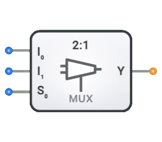
- Simbolo: El multiplexor se representa como un bloque rectangular con dos entradas de datos (D0, D1), una entrada de seleccion (Sel) y una unica salida (Y).
- Rol en DigiSim.io: El multiplexor de DigiSim.io es un MUX de 2 a 1 (2:1) que selecciona entre dos entradas de datos basandose en una unica linea de seleccion, sirviendo como componente fundamental de seleccion de datos en circuitos digitales.
Descripcion funcional
Comportamiento logico
El multiplexor de DigiSim.io es un MUX de 2 a 1. Usa una unica entrada de seleccion (Sel) para determinar cual de las dos entradas de datos (D0 o D1) se envia a la salida (Y). Cuando Sel=0, la salida Y es igual a D0. Cuando Sel=1, la salida Y es igual a D1.
Tabla de verdad (Multiplexor 2 a 1):
| Sel | D0 | D1 | Y |
|---|---|---|---|
| 0 | 0 | X | 0 |
| 0 | 1 | X | 1 |
| 1 | X | 0 | 0 |
| 1 | X | 1 | 1 |
Entradas y salidas
Entradas (3 en total):
- D0 (Dato 0): Entrada de datos de 1 bit, seleccionada cuando Sel=0.
- D1 (Dato 1): Entrada de datos de 1 bit, seleccionada cuando Sel=1.
- Sel (Seleccion): Entrada de control de 1 bit que determina cual entrada de datos (D0 o D1) aparece en la salida.
Salida (1 en total):
- Y (Salida): Salida de 1 bit que refleja el valor de la entrada de datos seleccionada.
Parametros configurables
- Retardo de propagacion: El tiempo que tarda la salida en cambiar despues de un cambio en la seleccion o la entrada.
Representacion visual en DigiSim.io
El multiplexor se muestra como un bloque rectangular con las dos entradas de datos (D0, D1) en un lado y la entrada de seleccion (Sel) tipicamente en la parte inferior. La salida (Y) esta en el lado opuesto. Cuando se conecta en un circuito, el componente indica visualmente la ruta de datos activa y los estados logicos a traves de cambios de color en los cables de conexion.
Valor educativo
Conceptos clave
- Seleccion de datos: Demuestra el concepto de elegir una senal de multiples opciones.
- Conmutacion digital: Ilustra como los sistemas digitales enrutan datos dinamicamente.
- Codificacion binaria: Muestra como los valores de seleccion binarios corresponden a rutas de datos especificas.
- Logica combinacional: Introduce como se pueden implementar funciones logicas complejas usando multiplexores.
Objetivos de aprendizaje
- Comprender como los multiplexores dirigen el flujo de datos en sistemas digitales.
- Aprender como los codigos de seleccion binarios determinan cual entrada se enruta a la salida.
- Reconocer el papel de los multiplexores en la creacion de sistemas digitales mas grandes.
- Aplicar multiplexores para implementar diversas funciones logicas combinacionales.
- Comprender como los multiplexores pueden reducir el conteo de componentes en ciertos disenos de circuitos.
Ejemplos de uso
- Seleccion de datos: Seleccionar una de multiples fuentes de datos para ser procesada.
- Sistemas de bus: Controlar que dispositivo obtiene acceso a un bus de datos compartido.
- Implementacion de logica: Implementar cualquier funcion logica combinacional usando un multiplexor con constantes y variables como entradas.
- Conversion paralelo a serie: Seleccionar bits secuencialmente de una entrada paralela.
- Sistemas de memoria: Direccionar y seleccionar celdas o palabras de memoria especificas.
Notas tecnicas
- El numero de lineas de seleccion (S) y el numero de entradas de datos (I) tienen una relacion: 2^S = I. Por ejemplo, el multiplexor 2 a 1 de DigiSim.io usa 1 linea de seleccion para elegir entre 2 entradas de datos.
- La conexion en cascada de multiples multiplexores permite la creacion de multiplexores mas grandes. Por ejemplo, dos multiplexores 4:1 y un multiplexor 2:1 pueden crear un multiplexor 8:1.
- Los multiplexores se pueden combinar con demultiplexores para crear sistemas de enrutamiento de datos bidireccional.
- En implementaciones fisicas, los multiplexores pueden experimentar breves fallos en la salida durante las transiciones de la linea de seleccion.
Caracteristicas
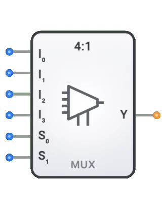
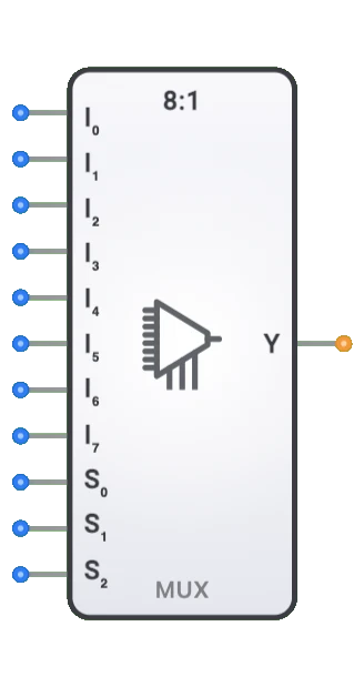
- Conteo de canales: Descrito como N:1 (por ejemplo, 2:1, 4:1, 8:1, 16:1)
- Lineas de seleccion: log2(N) entradas de seleccion para elegir entre N entradas de datos
- Retardo de propagacion: Tiempo entre el cambio de entrada y la salida estable
- Fan-out: Numero de puertas logicas que puede controlar
- Consumo de energia: Tipicamente aumenta con el conteo de canales
- Control de habilitacion: Algunos multiplexores incluyen una entrada de habilitacion
- Ancho de datos: Puede ser de 1 bit o multiples bits (multiplexores de bus)
- Inmunidad a fallos: Calidad para evitar salidas incorrectas transitorias durante transiciones
Tipos de multiplexores
Multiplexores binarios
- 2:1 (1 linea de seleccion)
- 4:1 (2 lineas de seleccion)
- 8:1 (3 lineas de seleccion)
- 16:1 (4 lineas de seleccion)
Multiplexores de bus
- Manejan multiples bits en paralelo
- Anchos comunes: 4 bits, 8 bits, 16 bits, 32 bits
Multiplexores analogicos
- Conmutan senales analogicas
- Mantienen la integridad de la senal con baja resistencia cuando estan encendidos
Multiplexores en arbol
- Construidos conectando en cascada multiplexores mas pequenos
- Se usan para implementaciones a gran escala
Multiplexores bidireccionales
- Permiten el flujo de senal en cualquier direccion
- Se usan en buses bidireccionales
Aplicaciones
Seleccion y enrutamiento de datos
- Seleccionar entre multiples fuentes de datos
- Multiplexado de direcciones de memoria en DRAM
- Arbitraje de bus en sistemas informaticos
Sistemas de comunicacion
- Multiplexado por division de tiempo (TDM) para comparticion de canales
- Seleccion de lineas en telecomunicaciones
- Aplicaciones de conmutacion de red
Implementacion de logica
- Implementar funciones booleanas
- Tablas de consulta (LUTs) en FPGAs
- Arreglos de logica programable
Pruebas y depuracion
- Sondeo y monitoreo de senales
- Seleccion de puntos de prueba
- Enrutamiento de senales de diagnostico
Circuitos aritmeticos
- Seleccion de funciones de ALU
- Operaciones condicionales
- Funciones de manipulacion de bits
Sistemas de control
- Seleccion de modo de operacion
- Configuracion de ruta de senales
- Implementaciones de maquinas de estados
Implementacion
Los multiplexores se pueden implementar usando:
Puertas logicas basicas
- Puertas AND, OR y NOT
- Puertas de transmision
Circuitos integrados
- Serie 74xx:
- 74157: Multiplexor cuadruple 2:1
- 74153: Multiplexor dual 4:1
- 74151: Multiplexor 8:1
- 74150: Multiplexor 16:1
- Serie 74xx:
Nivel de transistor
- Transistores de paso CMOS
- Puertas de transmision
- Buferes tri-estado
Disenos en HDL (Verilog/VHDL)
- Sentencias case
- Asignaciones condicionales
- Disenos parametrizados
Implementacion del circuito (MUX 2:1)
Un multiplexor basico 2:1 se puede implementar usando puertas logicas basicas:
Implementacion con puertas AND-OR
graph LR
    Input0[Input I0] --> AndGate0[AND Gate]
    SelectS[Select S] --> NotGate[NOT Gate]
    NotGate --> AndGate0

    Input1[Input I1] --> AndGate1[AND Gate]
    SelectS --> AndGate1

    AndGate0 --> OrGate[OR Gate]
    AndGate1 --> OrGate
    OrGate --> OutputY[Output]
Implementacion con puerta de transmision
graph LR
    Input0[Input I0] --> TransGate0[Transmission Gate 0]
    Input1[Input I1] --> TransGate1[Transmission Gate 1]

    TransGate0 --> OutputY[Output]
    TransGate1 --> OutputY

    SelectS[Select S] --> TransGate1
    SelectS --> NotGate[NOT Gate]
    NotGate --> TransGate0
Componentes relacionados
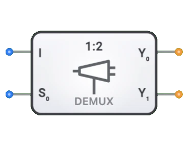
- Demultiplexores: Realizan la operacion inversa (enrutamiento de 1 a N)
- Codificadores: Convierten multiples lineas de entrada a codigo binario
- Decodificadores: Convierten codigo binario a multiples lineas de salida
- Transceptores de bus: Transferencia de datos bidireccional con control de direccion
- Selectores: Similares a los multiplexores pero con logica de control diferente
- Conmutadores de barra cruzada: Red de multiplexores para interconexion flexible
- Codificadores de prioridad: Seleccionan la entrada de mayor prioridad
- Conmutadores digitales: Equivalentes electronicos de conmutadores mecanicos
- Arboles de multiplexores: Multiplexores en cascada para grandes conteos de entradas
- Arreglos de logica programable: Usan multiplexores como bloques de construccion