8位计数器
概述
- 用途:8位计数器是一种时序数字电路,在时钟脉冲作用下按序列遍历256个不同的状态(0到255)。它可以递增计数,并根据控制信号保持当前值或清除。
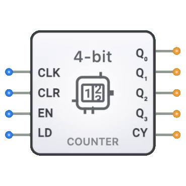
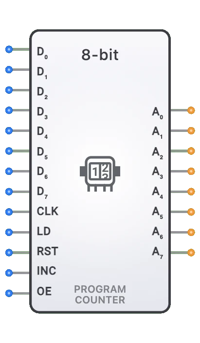
- 符号:8位计数器由矩形方块表示,包含时钟(CLK)、清除(CLR)、使能(EN)和加载(LD)输入,以及八个表示当前计数值的数据输出和一个进位输出。
- DigiSim.io 角色:作为数字系统中实现定时、排序和计数功能的基本组件,提供比较小计数器更大的范围(256个状态),适用于需要更多计数状态的应用。

功能描述
逻辑行为
8位计数器在使能时,每个时钟上升沿按二进制序列递增。仅向上计数。清除时,计数器异步返回零,不受时钟影响。
操作表:
| CLR | EN | CLK | 操作 | 输出效果 |
|---|---|---|---|---|
| 1 | X | X | 清除(异步) | Q = 0 |
| 0 | 1 | ↑ | 递增计数 | Q[n+1] = Q[n] + 1 |
| 0 | 0 | ↑ | 保持 | Q[n+1] = Q[n] |
| 0 | X | 0 | 无变化 | Q[n+1] = Q[n] |
注:↑ 表示时钟上升沿,X 表示"无关"条件。计数器从255回绕到0。
输入和输出
输入:
- CLK(时钟):引脚 0。在上升沿触发计数器。
- CLR(清除):引脚 1。高电平时异步将计数器复位为0。
- EN(使能):引脚 2。高电平时使能计数。
- LD(加载):引脚 3。保留供将来使用(目前不支持并行加载)。
输出:
- Q[7:0]:8位输出,表示当前计数值(Q0=LSB, Q7=MSB)。
- Carry:1位输出,当计数器达到最大值(255)时变为高电平。
可配置参数
- 时钟边沿灵敏度:计数器响应上升沿还是下降沿。
- 复位类型:复位是同步的(仅在时钟沿)还是异步的(立即)。
- 复位值:计数器复位到的值(通常为零)。
- 计数序列:计数器遵循二进制、BCD还是其他计数序列。
- 传播延迟:触发事件后输出变化所需的时间。
DigiSim.io 中的视觉表示
8位计数器显示为矩形方块,左侧标注输入(CLK、RST、EN、UP/DOWN),右侧为输出(Q[7:0]、COUT)。时钟输入通常用三角形符号标记,表示边沿灵敏。在电路中连接时,组件通过输出上显示的二进制值和连接线的颜色变化直观显示其当前状态。
教育价值
核心概念
- 时序逻辑:演示数字电路如何随时间维护和更新状态。
- 二进制计数:说明二进制数序列的递进。
- 同步操作:展示时钟信号如何协调和同步数字操作。
- 模运算:介绍当计数器超出范围时的溢出/回绕概念。
- 控制逻辑:介绍使用使能和方向控制来修改电路行为。
学习目标
- 理解计数器如何遍历二进制序列并维护状态。
- 学习复位、使能和方向等控制信号如何影响计数器操作。
- 认识同步和异步计数器设计之间的区别。
- 将8位计数器应用于设计定时器、排序器和地址生成器。
- 理解计数器溢出/下溢的概念以及进位输出如何指示这些条件。
使用示例/场景
- 地址生成:在CPU或控制器中顺序访问内存位置。
- 定时器实现:创建精确的时间延迟或测量时间间隔。
- 事件计数:统计数字系统中事件或脉冲的发生次数。
- 分频:将输入时钟频率按可编程因子分频。
- 状态排序:实现有限状态机的排序逻辑。
- 数据采集:控制模拟信号采样的时序。
- 数字控制系统:生成控制操作的定时序列。
技术说明
- 8位计数器可以使用多种架构实现:
- 异步(行波)计数器:简单但在各位位置之间存在传播延迟问题。
- 同步计数器:所有触发器同时变化,提供更可靠的时序。
- 8位二进制计数器可表示从0到255的值,然后回绕。
- 最大工作频率受计数器逻辑中传播延迟的限制。
- 可以通过将一个计数器的进位输出连接到下一个计数器的使能来级联创建更宽的计数器(16位、32位)。
- 特殊计数器配置如约翰逊计数器或环形计数器为特定应用提供不同的计数序列。
- 在 DigiSim.io 中,计数器的行为模拟真实数字组件,正确处理控制输入和同步操作。
特性
输入配置:
- 时钟输入(CLK):触发状态转换,通常在上升沿有效
- 复位输入(RST):复位有效时异步将计数器清零
- 使能输入(EN):使能或禁用计数操作
- 方向控制(UP/DOWN):决定计数方向(高电平递增,低电平递减)
- 兼容标准数字逻辑电平
- 某些实现中可能包含附加输入(加载、预置等)
- 典型时钟频率范围:DC到50+ MHz,取决于技术
输出配置:
- 八个状态输出(Q0-Q7)
- 进位/借位输出(Cout)- 计数器溢出(递增)或下溢(递减)时有效
- 每个输出表示当前计数值的一位
- Q0 为最低有效位(LSB),Q7 为最高有效位(MSB)
- 能够驱动标准数字负载
- 某些实现中可能包含互补输出
功能:
- 从 0 到 255(或 255 到 0)按二进制序列计数
- 完整的8位范围提供256个不同状态
- 递增计数时从255回绕到0
- 递减计数时从0回绕到255
- 回绕条件产生进位输出
- 可配置不同的计数序列
- 使用附加逻辑可实现模N计数
传播延迟:
- 时钟到输出:典型 15-35ns
- 建立时间:时钟沿前 10-20ns
- 保持时间:时钟沿后 0-10ns
- 复位到输出:10-25ns
- 取决于技术(TTL、CMOS等)
- 同步设计具有一致的输出时序
- 级联异步实现中延迟更高
扇出:
- 通常驱动 10-20 个标准负载
- 输出负载影响传播延迟
- 高扇出应用可能需要缓冲
- 现代CMOS实现具有改进的驱动能力
功耗:
- CMOS实现中静态功耗最小
- 动态功耗随时钟频率增加
- 与改变状态的位数成正比
- 由于额外触发器,高于4位计数器
- 许多实现中具有功耗管理功能
- 在高速应用中可能显著
电路复杂度:
- 中等到高复杂度
- 需要八个触发器加控制逻辑
- 同步设计比异步更复杂
- 并行加载等功能需要额外逻辑
- 复杂度随功能集增加
- 集成版本减少外部组件数量
实现方法
异步(行波)计数器
- 八个触发器的级联(通常为T或JK型)
- 每个触发器输出驱动下一个的时钟
- 简单实现但有传播延迟问题
- LSB每个时钟变化,高位在被驱动时变化
- 不适合高速应用
- 转换期间可能出现毛刺
- 最简设计但有时序限制
同步计数器
- 所有触发器共享公共时钟
- 状态转换同时发生
- 附加组合逻辑决定哪些触发器翻转
- 比行波设计更复杂但时序更好
- 比异步设计速度更高
- 可预测的时序行为
- 可使用D、JK或T触发器实现
递增/递减二进制计数器
- 双向计数能力
- 每个触发器的方向控制逻辑
- 方向控制增加复杂度
- 在特定应用计数器中常见
- 可靠操作首选同步实现
- 两个计数方向的进位/借位逻辑
可预置计数器
- 包含并行加载能力
- 每位的数据输入
- 加载使能控制信号
- 可初始化为任意值
- 适用于特定间隔的定时
- 加载路径需要附加多路复用器
- 在可编程定时器应用中常见
二进制编码十进制(BCD)计数器
- 修改的8位计数器,具有两个BCD十进位
- 以十进制从0到99计数
- 每个4位段在计数10时的复位逻辑
- 适用于人可读的计数应用
- 在显示和用户界面中常见
- 更复杂的解码逻辑
集成电路实现
- 可作为专用计数器IC获得
- 74xx系列常见(74LS590、74HC590、74HC393级联)
- 各种功能:可预置、可级联、递增/递减
- 不同技术满足不同速度/功耗要求
- 可能包含三态输出等附加功能
- 减少系统设计中的组件数量
FPGA/ASIC实现
- 使用触发器和LUT高效实现
- 高度可配置和可优化
- 易于添加专用功能
- 通常从HDL描述综合而来
- 在现代可编程逻辑中资源高效
- 可针对特定时序要求定制
应用
内存寻址
- 微控制器和CPU中的程序计数器
- 顺序内存访问的地址生成
- DRAM刷新计数器
- 计算系统中的堆栈指针
- 内存传输的DMA控制器
- 遍历内存位置
定时生成
- 精确定时间隔(最多256个时钟周期)
- 可编程延迟生成
- 脉冲宽度控制
- 系统定时协调
- 实时时钟子系统
- 超时生成
分频
- 分频比最多256的时钟分频器
- 精确频率合成
- 信号生成器
- 通信的波特率生成器
- 数字系统中的时钟管理
- 频率缩放
事件计数
- 高范围事件统计
- 仪器中的脉冲计数
- 转速计数
- 流量测量
- 发生率监控
- 生产线计数
数字控制系统
- 状态机实现
- 排序控制操作
- 电机控制定时
- 过程控制器
- 工业自动化排序
- 基于时间的控制算法
数据采集
- 采样定时控制
- ADC控制排序
- 数据缓冲地址
- 测量触发生成
- 采样率控制
- 降噪的平均计数器
通信系统
- 数据包的帧计数器
- 串行协议中的字节排序
- 通信定时
- 协议排序
- 错误检测计数器
- 位定时生成器
局限性
时序约束
- 最大工作频率受技术限制
- 可靠操作的建立时间和保持时间要求
- 复杂系统中的时钟偏斜问题
- 异步设计中的传播延迟累积
- 复位恢复时序要求
- 行波实现中所有位的时序不一致
毛刺和竞争条件
- 转换期间的输出毛刺(尤其在异步设计中)
- 多位转换期间的中间状态
- 在控制应用中至关重要
- 可能错误触发下游逻辑
- 输出解码逻辑中的冒险
- 计数器反馈路径中的竞争条件
范围限制
- 限于8位值(0-255)
- 更大计数范围需要级联
- 超出范围计数的溢出处理
- 非二进制序列需要额外逻辑
- 模N计数需要附加逻辑
- 对小计数范围效率低
功耗
- 快速时钟率下高动态功耗
- 多位转换时功耗峰值
- 电池供电应用中影响显著
- 随开关频率增加
- 由于更多触发器,高于较小计数器
- 高速操作中的热考虑
设计复杂度
- 比较小计数器更复杂
- 高级功能增加逻辑需求
- 同步设计需要更多组合逻辑
- 测试和验证复杂度
- 增加的组件数量或逻辑资源
- 关键应用中复杂的时序分析
电路实现细节
8位同步二进制递增计数器
graph TB
    Clock[Clock CLK] --> FlipFlop0[Flip-Flop 0]
    Clock --> FlipFlop1[Flip-Flop 1]
    Clock --> FlipFlop2[Flip-Flop 2]
    Clock --> DOTS[...]
    Clock --> FlipFlop7[Flip-Flop 7]

    Reset[Reset RST] --> FlipFlop0
    Reset --> FlipFlop1
    Reset --> FlipFlop2
    Reset --> DOTS
    Reset --> FlipFlop7

    FlipFlop0 --> OutputQ0[Q0]
    FlipFlop1 --> OutputQ1[Q1]
    FlipFlop2 --> OutputQ2[Q2]
    DOTS --> QDOTS[...]
    FlipFlop7 --> OutputQ7[Q7]

    ControlLogic[Enable & Clock<br/>Control Logic]
    Enable[Enable EN] --> ControlLogic
    UpDown[UP/DOWN] --> ControlLogic
    ControlLogic -.-> FlipFlop0
    ControlLogic -.-> FlipFlop1
    ControlLogic -.-> FlipFlop2
    ControlLogic -.-> FlipFlop7
74HC590 带输出寄存器的8位二进制计数器
    ┌─────────────────┐
    │                 │
    │     74HC590     │
    │                 │
CLK ┤CP            Q0 ├── Q0
    │                 │
MR  ┤MR            Q1 ├── Q1
    │                 │
    │               Q2 ├── Q2
    │                 │
    │               Q3 ├── Q3
    │                 │
    │               Q4 ├── Q4
    │                 │
    │               Q5 ├── Q5
    │                 │
    │               Q6 ├── Q6
    │                 │
    │               Q7 ├── Q7
    │                 │
CEP ┤CEP              │
    │                 │
CET ┤CET          Q7S ├── Cout
    │                 │
OE  ┤OE               │
    │                 │
RCK ┤RCK              │
    │                 │
    └─────────────────┘
CP = 时钟脉冲输入, MR = 主复位, CEP/CET = 计数使能输入, OE = 输出使能, RCK = 寄存器时钟, Q7S = 进位输出
相关组件
- 4位计数器:范围 0-15 的较小计数器
- 16位计数器:范围 0-65535 的扩展计数器
- BCD计数器:按十进制数位序列计数
- 递增/递减计数器:具有方向控制的双向计数器
- 可加载计数器:具有并行数据加载能力的计数器
- 约翰逊计数器:带反向反馈的移位寄存器,每个状态只有一位变化
- 环形计数器:带直接反馈的移位寄存器,循环单个位
- 级联计数器:多个计数器连接以扩展计数范围
- 分频器:专门用于时钟分频的计数器
- 程序计数器:处理器中用于指令排序的专用计数器