Porte ET (AND)
Vue d'ensemble
- Objectif : La porte ET effectue une opération logique ET sur ses entrées. La sortie est à l'état HAUT (logique « 1 ») uniquement lorsque toutes les entrées sont à l'état HAUT. Si une entrée est à l'état BAS (logique « 0 »), la sortie est à l'état BAS.
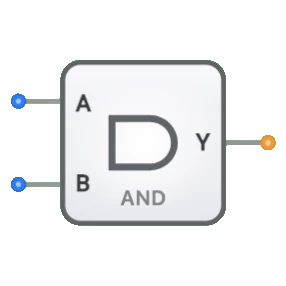
- Symbole : La porte ET est représentée par un symbole en forme de D, avec un côté entrée plat et un côté sortie incurvé.
- Rôle de DigiSim.io : Sert de bloc de construction fondamental dans les circuits de logique numérique, en mettant en œuvre l'opération booléenne ET.
Description fonctionnelle
Comportement logique
La porte ET implémente la conjonction logique, produisant une sortie HAUTE uniquement lorsque toutes les entrées sont à l'état HAUT.
Table de vérité (porte ET à 2 entrées) :
| Entrée A | Entrée B | Sortie Y |
|---|---|---|
| 0 | 0 | 0 |
| 0 | 1 | 0 |
| 1 | 0 | 0 |
| 1 | 1 | 1 |
Expression booléenne : Y = A · B (Y égale A ET B)
Entrées et sorties
- Entrées : La porte ET dispose de 2 entrées (A, B).
- Sortie : Une unique sortie 1 bit représentant le résultat de l'opération ET.
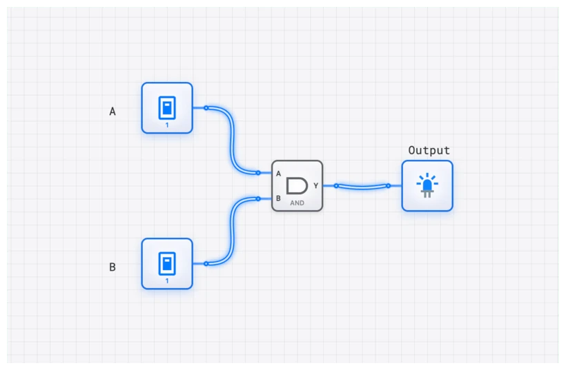
Représentation visuelle dans DigiSim.io
La porte ET affiche ses broches d'entrée à gauche et sa broche de sortie à droite. La porte utilise le symbole standard en forme de D avec un côté droit incurvé. Lorsqu'elle est connectée dans un circuit, le composant indique visuellement l'état logique de ses broches par des changements de couleur sur les fils de connexion.
Valeur pédagogique
Concepts clés
- Algèbre de Boole : Renforce la notion d'opérateur logique ET dans les expressions booléennes.
- Logique combinatoire : Illustre un circuit de logique combinatoire fondamental dont la sortie ne dépend que des valeurs d'entrée actuelles.
- Tables de vérité : Aide à comprendre comment lire et interpréter le comportement d'une porte logique au moyen de tables de vérité.
- Conjonction logique : Illustre la notion de conjonction logique en logique propositionnelle.
Objectifs d'apprentissage
- Comprendre l'opération logique ET et sa représentation par table de vérité.
- Apprendre comment les portes ET servent de blocs de construction pour des circuits numériques plus complexes.
- Reconnaître les conventions de symboles standard pour les portes logiques en électronique numérique.
- Appliquer l'opération ET pour résoudre des problèmes de logique du monde réel.
- Identifier la relation entre la fonction ET et son implémentation matérielle.
Exemples d'utilisation
- Vérification de conditions : Utilisée pour vérifier que plusieurs conditions sont simultanément vraies avant de poursuivre une action.
- Validation des données : Dans les systèmes informatiques, les portes ET garantissent que tous les critères sont remplis avant qu'une opération ne soit effectuée.
- Contrôle par grille : Contrôle le passage d'un signal en fonction d'un signal d'activation (une entrée est la donnée, l'autre la commande).
- Masquage de bits : Extraction de bits spécifiques d'un nombre binaire par un ET avec un masque.
- Systèmes de sécurité : Garantir que plusieurs conditions de sécurité sont remplies avant d'accorder l'accès.
Notes techniques
- Les portes ET peuvent être implémentées à l'aide de diverses technologies, dont la logique transistor-transistor (TTL) et la logique CMOS (semi-conducteur métal-oxyde complémentaire).
- Le temps de propagation d'une porte ET dépend de la technologie utilisée et augmente légèrement avec le nombre d'entrées.
- Plusieurs portes ET peuvent être combinées avec d'autres portes logiques pour créer des fonctions logiques complexes.
- En conception de circuits numériques, les portes ET sont souvent utilisées conjointement avec les portes OU et NON pour implémenter n'importe quelle fonction booléenne.
- Dans DigiSim.io, le comportement de la porte ET simule celui des composants numériques réels, y compris la gestion correcte des entrées indéfinies.