Demultiplexor
Descripcion general
- Proposito: El demultiplexor (DEMUX) es un componente digital que enruta una unica senal de entrada a una de dos posibles salidas segun una entrada de seleccion. Funciona como un distribuidor de datos, dirigiendo informacion de una fuente a uno de dos destinos.
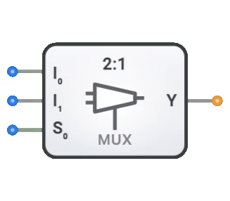
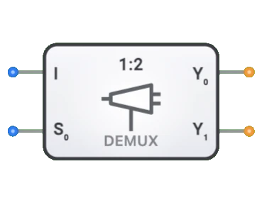
- Simbolo: El demultiplexor se representa como un bloque rectangular con una unica entrada de datos, una entrada de seleccion y dos lineas de salida.
- Rol en DigiSim.io: Sirve como componente fundamental de distribucion de datos 1 a 2 en circuitos digitales, permitiendo el enrutamiento de senales, la decodificacion de direcciones y la implementacion de sistemas digitales complejos.
Descripcion funcional
Comportamiento logico
El demultiplexor dirige la senal de entrada a una de dos salidas segun el valor de la entrada de seleccion. Cuando Sel=0, la entrada Data se enruta a Y0 mientras Y1 se mantiene en 0. Cuando Sel=1, la entrada Data se enruta a Y1 mientras Y0 se mantiene en 0.
Tabla de verdad (Demultiplexor 1 a 2):
| Data | Sel | Y0 | Y1 |
|---|---|---|---|
| 0 | 0 | 0 | 0 |
| 0 | 1 | 0 | 0 |
| 1 | 0 | 1 | 0 |
| 1 | 1 | 0 | 1 |
Nota: Cuando Data es 0, ambas salidas son 0 independientemente de la entrada de seleccion.
Entradas y salidas
Entradas (2 en total):
- Data: Entrada de datos de 1 bit que sera dirigida a una de las dos salidas.
- Sel: Entrada de seleccion de 1 bit que determina que salida recibe la senal de datos.
Salidas (2 en total):
- Y0: Salida que recibe la entrada Data cuando Sel=0.
- Y1: Salida que recibe la entrada Data cuando Sel=1.
Parametros configurables
- Retardo de propagacion: El tiempo que tardan las salidas en cambiar despues de un cambio en la seleccion o la entrada.
Representacion visual en DigiSim.io
El demultiplexor se muestra como un bloque rectangular con una unica entrada de datos en un lado (tipicamente el izquierdo), una entrada de seleccion generalmente en la parte inferior y dos salidas (Y0, Y1) en el lado opuesto. Cuando se conecta en un circuito, el componente indica visualmente la ruta de salida activa mediante cambios de color en los cables de conexion.
Valor educativo
Conceptos clave
- Distribucion de datos: Demuestra como una unica senal puede ser enrutada a diferentes destinos.
- Decodificacion binaria: Ilustra como los valores binarios pueden ser decodificados para seleccionar salidas especificas.
- Conmutacion digital: Muestra como los sistemas digitales pueden redirigir senales dinamicamente.
- Operaciones de uno a muchos: Introduce el concepto de distribuir una senal a multiples receptores potenciales.
Objetivos de aprendizaje
- Comprender como los demultiplexores dirigen el flujo de datos de una fuente a multiples destinos.
- Aprender la relacion entre codigos de seleccion binarios y salidas activas.
- Reconocer como los demultiplexores pueden usarse para la decodificacion de direcciones en sistemas de memoria.
- Aplicar demultiplexores en el diseno de sistemas de distribucion de datos.
- Comprender la relacion complementaria entre multiplexores y demultiplexores.
Ejemplos de uso/Escenarios
- Decodificacion de direcciones: Seleccion de chips de memoria o perifericos especificos segun valores de direccion.
- Distribucion de datos: Enrutamiento de datos de una unica fuente a multiples dispositivos de destino.
- Conversion serie a paralelo: Distribucion de bits de un flujo serie a salidas paralelas.
- Enrutamiento de senales de control: Direccion de senales de control a componentes especificos en un sistema mas grande.
- Sistemas de visualizacion: Seleccion de segmentos o digitos individuales en pantallas de multiples elementos.
Notas tecnicas
- El numero de lineas de seleccion (S) y el numero de salidas (Y) tienen una relacion: 2^S = Y. El demultiplexor 1 a 2 de DigiSim.io usa 1 linea de seleccion (2^1 = 2 salidas).
- Los demultiplexores se usan frecuentemente junto con multiplexores para crear sistemas completos de enrutamiento de datos.
- Un demultiplexor puede considerarse como un decodificador con una entrada de habilitacion que actua como la entrada de datos.
- Para sistemas activos en bajo, las salidas inactivas pueden estar en ALTO en lugar de BAJO, con solo la salida seleccionada estando en BAJO cuando la entrada es BAJO.
Caracteristicas
- Cantidad de canales: Descrito como 1:N (p. ej., 1:2, 1:4, 1:8, 1:16)
- Lineas de seleccion: log2(N) entradas de seleccion para elegir entre N salidas
- Retardo de propagacion: Tiempo entre el cambio de entrada y la salida estable
- Fan-Out: Numero de compuertas logicas que puede alimentar desde cada salida
- Consumo de energia: Tipicamente aumenta con la cantidad de canales
- Control de habilitacion: Algunos demultiplexores incluyen una entrada de habilitacion
- Ancho de datos: Puede ser de 1 bit o multi-bit (demultiplexores de bus)
- Inmunidad a glitches: Calidad para evitar salidas incorrectas transitorias durante transiciones
Tipos de demultiplexores
Demultiplexores binarios
- 1:2 (1 linea de seleccion)
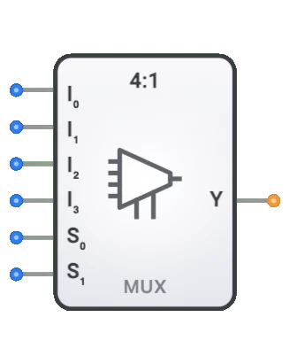
- 1:4 (2 lineas de seleccion)
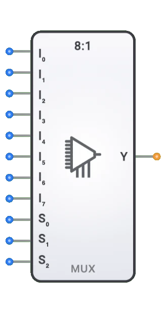
- 1:8 (3 lineas de seleccion)
- 1:16 (4 lineas de seleccion)
Demultiplexores de bus
- Manejan multiples bits en paralelo
- Anchos comunes: 4 bits, 8 bits, 16 bits, 32 bits
Demultiplexores activos en bajo
- La salida esta activa cuando es baja
- Comun en ciertas familias logicas
Demultiplexores activos en alto
- La salida esta activa cuando es alta
- Comportamiento estandar en la mayoria de los sistemas digitales
Demultiplexores en arbol
- Construidos conectando en cascada demultiplexores mas pequenos
- Usados para implementaciones a gran escala
Aplicaciones
Distribucion de datos
- Distribucion de senales a multiples destinos
- Seleccion de banco de memoria
- Seleccion de puerto de E/S
Decodificacion de direcciones
- Decodificacion de direcciones de memoria
- Seleccion de dispositivos perifericos
- Generacion de chip select
Sistemas de comunicacion
- Demultiplexacion por division de tiempo
- Separacion de canales
- Distribucion de flujos de datos
Sistemas de control
- Distribucion de modos de operacion
- Enrutamiento de senales de control
- Implementaciones de maquinas de estados
Almacenamiento de datos
- Control de habilitacion de escritura en memoria
- Seleccion de banco de almacenamiento
- Direccionamiento de archivo de registros
Sistemas de visualizacion
- Seleccion de segmentos en pantallas
- Direccionamiento de matrices
- Seleccion de pixeles
Implementacion
Los demultiplexores pueden implementarse usando:
Compuertas logicas basicas
- Compuertas AND con estructura de decodificador
- Combinacion de decodificador y compuertas AND
Circuitos integrados
- Serie 74xx:
- 74139: Demultiplexor dual 1:4
- 74138: Demultiplexor 1:8
- 74154: Demultiplexor 1:16
- Serie 74xx:
Nivel de transistor
- Redes de transistores CMOS
- Transistores de paso
- Buffers tri-estado
Disenos HDL (Verilog/VHDL)
- Sentencias case
- Asignaciones condicionales
- Disenos parametrizados
Implementacion del circuito (DEMUX 1:2)
Un demultiplexor basico de 1 a 2 puede implementarse usando compuertas logicas basicas:
graph TB
    Data[Data] --> AndGate0[AND Gate]
    Data --> AndGate1[AND Gate]

    Sel[Sel] --> NotGate[NOT Gate]
    Sel --> AndGate1
    NotGate --> AndGate0

    AndGate0 --> OutputY0[Y0]
    AndGate1 --> OutputY1[Y1]
Ecuaciones booleanas (DEMUX 1:2)
Para el demultiplexor 1 a 2 con entrada de datos D, salidas Y0 e Y1, y entrada de seleccion S:
- Y0 = D · S̅
- Y1 = D · S
Donde · representa AND logico y ̅ representa NOT logico
Componentes relacionados
- Multiplexores: Realizan la operacion inversa (enrutamiento N a 1)
- Decodificadores: Convierten codigo binario a multiples lineas de salida
- Codificadores: Convierten multiples lineas de entrada a codigo binario
- Transceptores de bus: Transferencia de datos bidireccional con control de direccion
- Distribuidores de datos: Similares a los demultiplexores pero con diferente logica de control
- Decodificadores de direcciones: Demultiplexores especializados para el direccionamiento de memoria
- Conmutadores digitales: Equivalentes electronicos de conmutadores mecanicos
- Arboles de demultiplexores: Demultiplexores en cascada para grandes cantidades de salidas