Eingangsschalter
Überblick
- Zweck: Der Eingangsschalter ist eine digitale Komponente, die eine manuelle Steuerung eines binären Signalwerts ermöglicht. Er wandelt eine Benutzeraktion in ein logisches HIGH- oder LOW-Signal um und stellt so einen interaktiven Eingang für digitale Schaltungen bereit.
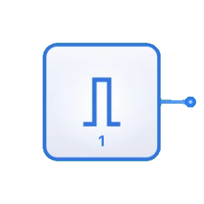
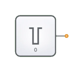
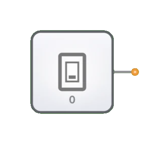
- Symbol: Der Eingangsschalter wird durch das Symbol eines Kippschalters mit einem Ausgangspin dargestellt.
- Rolle in DigiSim.io: Bietet einen vom Anwender gesteuerten Eingangsmechanismus für digitale Schaltungen in der Simulationsumgebung und ermöglicht das interaktive Testen und Demonstrieren des Schaltverhaltens.
Funktionsbeschreibung
Logikverhalten
Der Eingangsschalter gibt einen konstanten Binärwert aus, der vom Benutzer manuell zwischen HIGH und LOW umgeschaltet werden kann.
Zustände:
| Schalterstellung | Ausgangswert |
|---|---|
| Stellung OFF | 0 (LOW) |
| Stellung ON | 1 (HIGH) |
Ein- und Ausgänge
- Eingänge: Keine. Der Eingangsschalter wird direkt durch Benutzerinteraktion gesteuert und nicht durch logische Eingänge.
- Ausgang: Ein einzelner 1-Bit-Ausgang, der je nach Schalterstellung ein HIGH- oder LOW-Signal liefert.
Konfigurierbare Parameter
- Anfangszustand: Die Ausgangsposition des Schalters (ON oder OFF).
- Beschriftung: Optionaler Text, mit dem der Zweck des Schalters in der Schaltung gekennzeichnet werden kann.
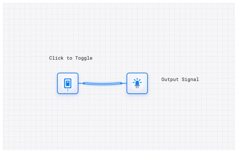
Visuelle Darstellung in DigiSim.io
Der Eingangsschalter wird als Kippschalter dargestellt, der durch Anklicken seinen Zustand wechselt. In der ON-Stellung zeigen Schalter und zugehörige Ausgangsleitung über Farbänderungen den HIGH-Zustand an. In der OFF-Stellung wird entsprechend der LOW-Zustand visualisiert. Die grafische Darstellung macht jederzeit deutlich, in welcher Stellung sich der Schalter befindet.
Didaktischer Wert
Schlüsselkonzepte
- Signalerzeugung: Demonstriert das Konzept binärer Signalquellen in digitalen Systemen.
- Benutzerschnittstelle: Veranschaulicht, wie menschliche Eingaben in digitale Signale übersetzt werden.
- Steuerfluss: Zeigt, wie Eingangssignale das Schaltverhalten bestimmen.
- Zustandssteuerung: Führt die manuelle Festlegung von Zuständen in digitalen Schaltungen ein.
Lernziele
- Verstehen, wie Binäreingänge das Verhalten digitaler Schaltungen beeinflussen.
- Schalter zum Testen und Verifizieren der Schaltungsfunktion einsetzen lernen.
- Die Rolle von Benutzereingaben im Entwurf digitaler Systeme erkennen.
- Eingangsschalter korrekt einsetzen, um interaktive digitale Systeme zu erstellen.
- Fähigkeiten beim Debuggen von Schaltungen mithilfe gesteuerter Eingaben aufbauen.
Anwendungsbeispiele/Szenarien
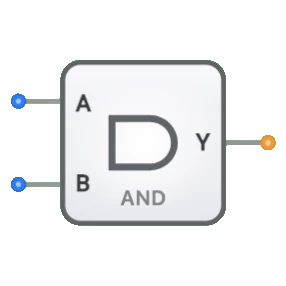
- Logiktest: Verifizieren des Verhaltens von Logikgattern und kombinatorischen Schaltungen.
- Festlegung von Anfangsbedingungen: Definieren der Startzustände für sequentielle Schaltungen.
- Modusauswahl: Aktivieren oder Deaktivieren bestimmter Funktionen in einem digitalen System.
- Manuelle Dateneingabe: Eingeben binärer Datenwerte zur Verarbeitung.
- Steuersignale: Bereitstellen von Steuersignalen für Komponenten wie Multiplexer, Decodierer oder Freigabeleitungen.
Technische Hinweise
- Im Gegensatz zur Taktkomponente, die periodische Signale automatisch erzeugt, behält der Eingangsschalter seinen Zustand bei, bis er manuell verändert wird.
- Mehrere Eingangsschalter können kombiniert werden, um Mehrbit-Eingaben für Binärwerte zu erzeugen.
- In DigiSim.io reagieren Schalter unmittelbar auf das Umschalten, während physische Schalter Schaltungen zur Entprellung erfordern können.
- Mit dem Eingangsschalter lassen sich bestimmte Schaltungsteile gezielt isolieren und debuggen, indem die Eingangsbedingungen präzise gesteuert werden.
Implementierung
In realen Anwendungen werden Eingangsschalter realisiert durch:
- Mechanische Kipp- oder Tastschalter mit Entprellschaltungen
- DIP-Schalter (Dual In-line Package) für Konfigurationseinstellungen
- Touchscreen- oder Tastatureingaben in Software-Simulationen
- Relaiskontakte in einigen industriellen Anwendungen
Verwandte Komponenten
- Takt: Liefert ein automatisch wechselndes Signal, anders als der manuell gesteuerte Eingangsschalter
- Konstante: Liefert einen festen Wert (0 oder 1) ohne manuelles Eingreifen
- Taster: Eine momentane Variante des Schalters, die nach dem Loslassen in den Ausgangszustand zurückkehrt