XOR vs. XNOR: The Critical Difference in Error Detection
XOR detects difference; XNOR confirms equality. Multi-input chains form odd- and even-parity detectors. Includes a step-by-step 4-bit parity-check build.

TL;DR: XOR outputs 1 when inputs differ; XNOR outputs 1 when they match. Multi-input XOR chains detect odd parity; multi-input XNOR chains detect even parity. The choice between them depends on whether downstream logic expects “no error” as a 0 or a 1.
The XOR gate is the foundation of arithmetic, error detection, and data comparison. Its complement XNOR is the equality detector. The two gates are always opposite for any input combination, but the parity-detection behavior of their multi-input chains has real implications for error-detection circuits — covered below alongside a working 4-bit parity checker.
What is XOR (Exclusive OR)?
The XOR gate (Exclusive-OR) outputs 1 when the inputs are different. Unlike regular OR (which is “inclusive” — true when EITHER or BOTH), XOR is “exclusive” — true when EXACTLY ONE input is true.
XOR: Different Inputs = Output 1
Outputs 1 when A and B are different.
Outputs 0 when A and B are the same.
Boolean Expression:
| A | B | A XOR B | Meaning |
|---|---|---|---|
| 0 | 0 | 0 | Same (both 0) |
| 0 | 1 | 1 | Different |
| 1 | 0 | 1 | Different |
| 1 | 1 | 0 | Same (both 1) |
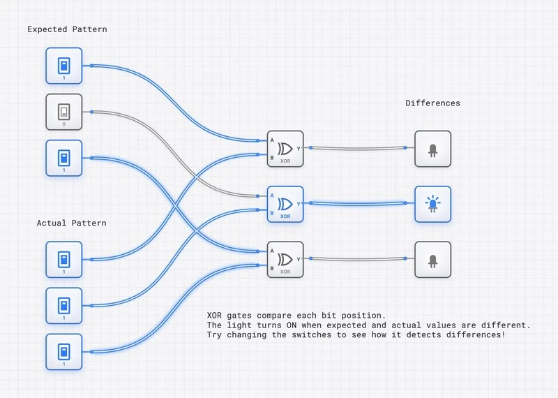
XOR gates comparing two 3-bit patterns. The middle light is ON because the middle bits differ — XOR detects the difference.
What is XNOR (Exclusive NOR)?
XNOR is the complement of XOR. It outputs 1 when inputs are the same, making it an equality detector.
XNOR: Same Inputs = Output 1
Outputs 1 when A and B are the same.
Outputs 0 when A and B are different.
Boolean Expression:
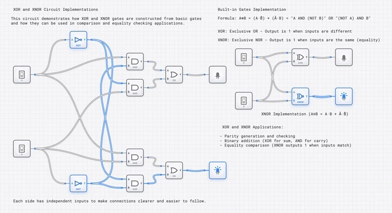
Side-by-side comparison of XOR and XNOR: with the same inputs, their outputs are always opposite.
The Complement Relationship: XOR vs. XNOR
The XOR and XNOR outputs are always complementary for any given input combination. This is the foundational relationship that determines their roles in error detection:
| A | B | XOR () | XNOR () | Interpretation |
|---|---|---|---|---|
| 0 | 0 | 0 | 1 | Equal — XNOR detects it |
| 0 | 1 | 1 | 0 | Different — XOR detects it |
| 1 | 0 | 1 | 0 | Different — XOR detects it |
| 1 | 1 | 0 | 1 | Equal — XNOR detects it |
When you extend this to multi-input chains:
- A chain of XOR gates is an odd-parity detector: output 1 when the number of HIGH inputs is odd. .
- An even-parity detector is built by taking the XOR-of-all-inputs and inverting the final output once (i.e., ). Equivalently, this is the behavior of a single wide XNOR primitive — not of a cascade of 2-input XNORs, which actually alternates polarity because .
This distinction is the critical difference in error detection. Both gates can detect single-bit errors, but they signal the error condition with opposite polarity. Choosing between them depends on whether your downstream logic expects the “no error” condition as a 0 or a 1.
XOR in Binary Addition
One of XOR’s most important applications is in adders. The half adder truth table reveals that the Sum output matches XOR exactly:
| A | B | A + B (Sum) | A XOR B | Match? |
|---|---|---|---|---|
| 0 | 0 | 0 | 0 | Yes |
| 0 | 1 | 1 | 1 | Yes |
| 1 | 0 | 1 | 1 | Yes |
| 1 | 1 | 0 (carry 1) | 0 | Yes |
XOR is exactly addition modulo 2 (ignoring the carry). Combined with AND for the carry, you get a complete half adder.
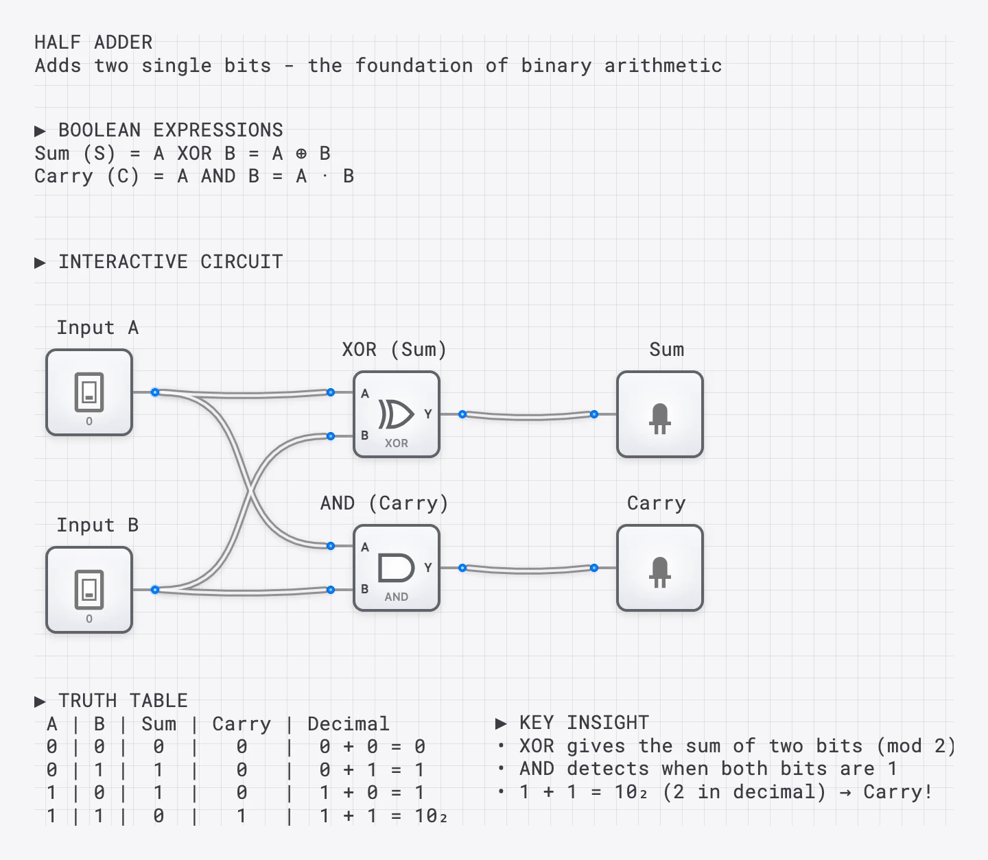
The half adder: XOR produces the sum, AND produces the carry. XOR is the foundation of all binary arithmetic.
Error Detection: Parity Bits in Depth
XOR’s most critical application is error detection. When transmitting data, bits can flip due to electrical noise, cosmic rays, or signal degradation. Parity checking detects these single-bit errors using XOR and XNOR.
How Parity Generation Works
Even Parity: Add a bit so the total number of 1s is even.
Odd Parity: Add a bit so the total number of 1s is odd.
Checking: XOR all received bits (including parity). If the result is 0, no error is detected. If the result is 1, an error occurred.
Consider sending 4 data bits with even parity:
Data:        1 0 1 1
Count of 1s: 3 (odd)
Parity bit:  1 (to make total even)
Transmitted: 1 0 1 1 1
At receiver: XOR all bits = (no error detected)
Now suppose the second bit flips during transmission:
Received:    1 1 1 1 1
XOR all:     1 ⊕ 1 ⊕ 1 ⊕ 1 ⊕ 1 = 1 (error detected!)
The parity check catches the single-bit error, but it cannot identify which bit flipped. For that, more sophisticated codes are needed.
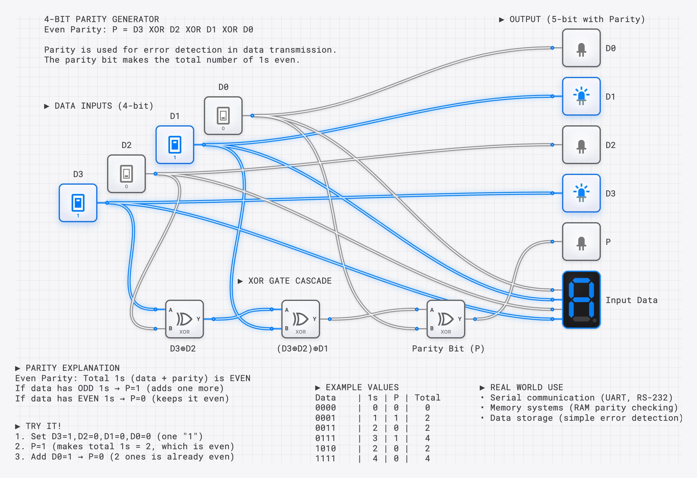
A 4-bit parity generator: an XOR chain calculates the parity bit. XORing all inputs (including parity) should give 0 if no errors.
XOR for Odd Parity, XNOR for Even Parity
Here is the critical practical difference:
- To generate an even parity bit, XOR all data bits. The result is the bit that, when appended, makes the total count of 1s even.
- To check even parity at the receiver, XOR all received bits (data + parity). Result 0 = no error; result 1 = error.
- Alternatively, use an XNOR chain as the checker: output 1 means even parity (no error); output 0 means odd parity (error detected).
In active-high alarm systems, XNOR is often preferred for the checker because the error condition (output going LOW) directly triggers an alert line.
Timing Analysis: Linear Chain vs. Balanced Tree
When building a parity generator for 8 data bits, the gate topology makes a significant difference:
- A linear chain of 7 XOR gates has a critical path of .
- A balanced binary tree (three levels: four XOR gates, then two, then one) has a critical path of only .
The balanced tree is more than 2x faster. In digisim.io, build both structures, connect them to the same CLOCK input, and observe on the OSCILLOSCOPE that the tree output settles well before the chain output. This difference becomes critical in high-speed systems where the parity must be computed within a single clock cycle.
Beyond Single-Bit: Hamming Codes
Simple parity can detect a single-bit error but cannot correct it. Hamming codes, invented by Richard Hamming at Bell Labs in 1950, use multiple parity bits computed over overlapping subsets of data bits to both detect and correct single-bit errors.
In a Hamming(7,4) code, 4 data bits are protected by 3 parity bits:
| Position | 1 | 2 | 3 | 4 | 5 | 6 | 7 |
|---|---|---|---|---|---|---|---|
| Type | P1 | P2 | D1 | P3 | D2 | D3 | D4 |
Each parity bit covers positions where the corresponding bit in the position’s binary representation is set:
- P1 (bit 0): positions 1, 3, 5, 7
- P2 (bit 1): positions 2, 3, 6, 7
- P3 (bit 2): positions 4, 5, 6, 7
Each parity bit is the XOR of its covered data positions. At the receiver, the three parity checks are recomputed. The resulting 3-bit “syndrome” identifies the exact position of any single-bit error, allowing automatic correction by flipping the identified bit with an XOR gate used as a controllable inverter.
The entire Hamming encoder and decoder can be built from XOR gates. This is an advanced but rewarding project on digisim.io.
XOR for Controlled Inversion
XOR has a special property: one input can control whether the other is inverted. This is essential in adder/subtractor circuits.
| Data | Control | Data XOR Control | Effect |
|---|---|---|---|
| 0 | 0 | 0 | Pass through |
| 1 | 0 | 1 | Pass through |
| 0 | 1 | 1 | Inverted |
| 1 | 1 | 0 | Inverted |
When Control = 0, the output equals Data (unchanged). When Control = 1, the output is NOT Data (inverted). This is how adder/subtractor circuits switch between and using two’s complement arithmetic.
Building a 4-Bit Parity Checker on digisim.io
Here is a step-by-step guide for building a complete parity checking system.
The Transmitter (Parity Generator)
- Place four INPUT_SWITCH components labeled D0, D1, D2, D3.
- Place three XOR gates in a balanced tree:
- XOR1: inputs D0 and D1.
- XOR2: inputs D2 and D3.
- XOR3: inputs are the outputs of XOR1 and XOR2.
- The output of XOR3 is the even parity bit (P).
- Connect an OUTPUT_LIGHT to P to see the generated parity bit.
The Channel (Error Injection)
- Place a fifth INPUT_SWITCH labeled “Error_Inject” and an XOR gate.
- Connect D1 and Error_Inject to this XOR gate. The output represents D1 after potential corruption. When Error_Inject = 0, D1 passes unchanged. When Error_Inject = 1, D1 is flipped.
The Receiver (Parity Checker)
- Build a second balanced XOR tree using the received bits: D0, corrupted-D1, D2, D3, and P.
- XOR all five signals through a tree of four XOR gates.
- Connect the final output to an OUTPUT_LIGHT labeled “ERROR”.
- When ERROR is lit (HIGH), a parity error has been detected.
Test procedure: Set D0-D3 to any pattern. Observe that ERROR stays OFF. Toggle Error_Inject to 1 — the ERROR light immediately turns ON. Toggle it back — ERROR turns OFF. You have built a working single-bit error detection system.
Use the OSCILLOSCOPE to compare the timing of the parity generator output versus the error detector output. The receiver has more gate levels, so its output settles later.
Applications Summary
| Domain | XOR Role | XNOR Role |
|---|---|---|
| Arithmetic | Sum bit in half/full adders | — |
| Subtraction | Controlled inversion (complement) | — |
| Comparison | Difference detection (inequality) | Equality detection (match) |
| Parity | Odd-parity detection / generation | Even-parity detection |
| Hamming codes | Syndrome computation, bit correction | — |
| Cryptography | XOR encryption () | — |
XOR Swap Algorithm
A classic trick for swapping two values without a temporary variable:
A = A ⊕ B
B = A ⊕ B
A = A ⊕ B
After these three operations, A and B have exchanged values. While elegant, this is primarily of academic interest today — modern compilers optimize register swaps more efficiently.
Try It Yourself
- Build a 4-bit parity generator and checker using the step-by-step guide above.
- Build a difference detector: Compare two 4-bit patterns with 4 XOR gates and an OR gate to flag any mismatch.
- Build an equality checker: Compare two 4-bit patterns with 4 XNOR gates and an AND gate to confirm a match.
- Compare linear chain vs. balanced tree: Build both for 8-bit parity and measure the delay difference with the OSCILLOSCOPE.
- Advanced challenge: Build a Hamming(7,4) encoder using XOR gates.
This is the third post in the XOR Family series. To revisit the individual gates, read The XOR Gate and The XNOR Gate. Open the XOR component reference and the XNOR component reference for direct truth-table verification.