The XNOR Gate: Champion of Equality in Digital Logic
The XNOR gate outputs 1 only when its inputs are identical. It is the equality detector behind every magnitude comparator, combination lock, and parity check.

TL;DR: The XNOR gate (Exclusive-NOR) outputs 1 only when its inputs are equal — both 0 or both 1. Boolean expression . Multi-input XNOR chains act as even-parity detectors, and pairing XNOR with AND produces magnitude comparators used in CPU equality checks.
The XNOR gate is the equality detector — it produces a HIGH output only when its inputs match. Where the XOR gate flags difference, XNOR confirms identity. That single behavior is what every magnitude comparator, combination lock, and even-parity checker depends on.
The Logic of Sameness: Defining the XNOR
The XNOR gate, short for Exclusive-NOR, is also known as the “equivalence gate” or “coincidence gate.” These names are perhaps more descriptive, as they perfectly capture its function. The gate produces a logical 1 (HIGH) when its inputs are equal—both 0 or both 1—and a 0 (LOW) when they are different.
In the hierarchy of digital systems, the XNOR gate sits just above the basic AND, OR, and NOT gates. While you can build an XNOR from those primitives, having it as a standalone component in digisim.io simplifies complex designs like magnitude comparators and parity generators.
Technical Specification: The Truth Table
To understand the XNOR, we have to look at its behavior across all possible input combinations. For a standard 2-input XNOR gate, the logic is unmistakable:
| Input A | Input B | Output Y |
|---|---|---|
| 0 | 0 | 1 |
| 0 | 1 | 0 |
| 1 | 0 | 0 |
| 1 | 1 | 1 |
Notice the pattern: the output Y is 1 only in the first and last rows, precisely where A is equal to B. This is the digital signature of equality. If you’re building a system that needs to trigger an event only when two sensors match, this is your go-to component.
The Boolean Expression for Equivalence
In Boolean algebra, the XNOR operation is the logical complement of the XOR operation. This relationship is the key to understanding its mathematical form. The symbol for XNOR is a circle with a dot inside: .
The output Y for inputs A and B can be expressed in two primary ways. First, as the inverse of XOR:
This is where the name “Exclusive-NOR” comes from—it is literally a NOT-XOR. However, when we’re designing circuits at the transistor level or optimizing logic, we often use the sum-of-products form, which directly reflects the truth table:
Let’s break this down. This equation states that the output Y is HIGH (1) if either of two conditions are met:
- A AND B are both HIGH ().
- OR both A AND B are both LOW ().
This beautifully encapsulates the logic of sameness in mathematical terms. It’s a “coincidence” detector; it only fires when the inputs coincide in value.
Building XNOR from Basic Gates
Understanding how to construct an XNOR gate from AND, OR, and NOT gates deepens your grasp of its internal logic and is essential for NAND-only or NOR-only design exercises.
Method 1: From the Sum-of-Products Expression
The SOP form translates directly into a circuit:
- AND Gate 1: Inputs and . Output: (both HIGH).
- NOT Gate 1: Input . Output: .
- NOT Gate 2: Input . Output: .
- AND Gate 2: Inputs and . Output: (both LOW).
- OR Gate: Inputs from AND Gate 1 and AND Gate 2. Output: the XNOR result.
Total: 2 NOT gates, 2 AND gates, 1 OR gate (5 gates).
Method 2: XOR Followed by NOT
Since XNOR is the complement of XOR (), the simplest construction is:
- XOR Gate: Inputs and .
- NOT Gate: Inverts the XOR output.
Total: 1 XOR gate + 1 NOT gate. This is the most common implementation in practice.
Method 3: NAND-Only Implementation
Using four NAND gates to build XOR, then one more NAND-as-inverter:
- Build the XOR circuit (4 NAND gates).
- Invert the output with a fifth NAND gate (inputs tied together).
Total: 5 NAND gates. Try this on digisim.io — it is a valuable exercise in NAND universality.
XOR vs. XNOR: The Complement Relationship
The XNOR gate is the exact logical complement of the XOR gate. Their outputs are always opposite for any given input combination:
| A | B | XOR () | XNOR () |
|---|---|---|---|
| 0 | 0 | 0 | 1 |
| 0 | 1 | 1 | 0 |
| 1 | 0 | 1 | 0 |
| 1 | 1 | 0 | 1 |
This complement relationship has a practical consequence for timing analysis. If you observe the XOR and XNOR outputs on an OSCILLOSCOPE simultaneously, you will see two waveforms that are perfect mirror images of each other — when one goes HIGH, the other goes LOW, with identical propagation delay. This makes XOR/XNOR pairs useful in differential signaling and balanced logic trees.
Key insight: XOR detects difference (output 1 when inputs disagree). XNOR detects equality (output 1 when inputs agree). Choosing between them depends on whether your downstream logic needs “match” or “mismatch” as the active signal.
Common Pitfall: The Multi-Input Trap
A 2-input XNOR gate is a straightforward equality checker. It is natural — and wrong — to assume that a 3-input or 4-input XNOR gate checks whether all inputs are the same.
It doesn’t. This is a critical distinction that can ruin a design if you aren’t careful.
In digital logic, an -input XNOR primitive — that is, with a single inversion applied to the XOR-of-all-inputs — functions as an even parity checker. It outputs a 1 if an even number of its inputs are 1, and a 0 if an odd number of its inputs are 1. (Note: this is the behavior of a wide XNOR built as one gate. A cascade of 2-input XNORs is not the same thing — see the next section.)
Let’s look at a 3-input XNOR gate to see why this happens:
- Inputs (0, 0, 0): Zero 1s (even). Output is 1. (Looks like equality!)
- Inputs (1, 1, 0): Two 1s (even). Output is 1. (Wait, these aren’t all the same!)
- Inputs (1, 1, 1): Three 1s (odd). Output is 0. (But they are all the same!)
If you need to check if three or more signals are all identical, you cannot use a single multi-input XNOR gate. Instead, you must use a series of 2-input XNOR gates fed into an AND gate. For example, to check if , you would check . Only if both comparisons are true can you say all three are equal.
Simulating on digisim.io: A Hands-On Guide
Theory is essential, but seeing logic propagation in real-time is where the “aha!” moments happen. Let’s build a verification circuit.
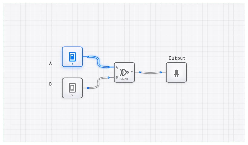
- Setup: Open digisim.io and drop an XNOR component onto the canvas.
- Inputs: Add two INPUT_SWITCH components. Label them ‘A’ and ‘B’ using the TEXT tool.
- Output: Connect the XNOR output to an OUTPUT_LIGHT.
- The Test: Toggle the switches. You’ll notice the light only glows when the switches match.
To see the key pitfall in action, try building a 3-input version by cascading two XNOR gates. Connect the output of the first XNOR (comparing A and B) to one input of a second XNOR, and use the third switch (C) as the other input. You’ll find the cascade produces the opposite of the 3-input XNOR primitive: it acts as odd parity, because — chaining XNORs cancels their negations in pairs. To get a true even-parity check from 2-input gates, use an XOR tree and invert the final output.
Real-World Application #1: The Magnitude Comparator
The most fundamental application of the XNOR gate is the digital comparator. How does a computer know if two numbers are equal? It doesn’t just “know”—it calculates it bit by bit.
Imagine you are designing a system that compares two 4-bit binary numbers, and . To determine if , every corresponding bit must match: must equal , must equal , and so on.
The circuit architecture looks like this:
- Four XNOR gates compare the individual bit pairs ().
- The outputs of these four gates are fed into a single 4-input AND gate.
- The AND gate only outputs HIGH if all four XNOR gates report “Equal.”
This logic is embedded in the COMPARATOR_8BIT component in digisim.io. This exact principle was used in the classic Intel 8086 processor’s ALU to execute “Jump if Equal” (JE) instructions. Every time you write if (x == y) in a high-level language, you are essentially firing a bank of XNOR gates.
Real-World Application #2: Error Detection with CRC
While simple parity checking uses XOR chains (odd-parity detection), more sophisticated error-detection schemes rely on the XNOR gate’s even-parity behavior.
In Cyclic Redundancy Check (CRC) implementations, data bits are processed through shift registers with feedback taps connected via XOR and XNOR gates. The choice between XOR and XNOR at each tap determines the generator polynomial. For example, CRC-8 uses the polynomial , which is implemented as a chain of flip-flops with XOR feedback at specific positions.
At the receiving end, the same CRC computation is performed on the received data (including the CRC checksum). If no errors occurred, the remainder is zero. The final comparison — checking whether the computed remainder equals the expected value — is performed bit-by-bit using XNOR gates fed into an AND gate, exactly like a magnitude comparator. If all bits match, the data is valid.
Real-World Application #3: Digital Combination Locks
Consider a 4-digit electronic combination lock. Each digit is represented as a 4-bit binary number. The lock stores a 4-bit secret code and compares it against the 4-bit input from the keypad.
The comparison circuit uses four XNOR gates (one per bit) feeding into a single AND gate. The door unlocks only when all four XNOR outputs are HIGH — meaning every bit of the entered code matches the stored code. This is the same XNOR-AND comparator architecture used in CPU equality checks, just applied to physical security.
You can build this on digisim.io:
- Place four pairs of INPUT_SWITCH components: four for the “secret code” and four for the “entered code.”
- Connect each pair to an XNOR gate.
- Feed all four XNOR outputs into a 4-input AND gate (or cascade two 2-input AND gates).
- Connect the AND output to an OUTPUT_LIGHT labeled “UNLOCK.”
- Only when all four switch pairs match will the light illuminate.
Real-World Application #4: Parity and Data Integrity
In data transmission, electrical noise can flip a bit from 0 to 1, corrupting your data. To catch these errors, engineers use “Parity Bits.”
In an Even Parity system, an extra bit is added to a data byte to ensure the total number of 1s is always even. If a 7-bit data string is 1101001 (four 1s), the parity bit is 0. If the data is 1001001 (three 1s), the parity bit is 1.
When the data arrives at its destination, an XNOR-based parity checker (recall the multi-input even-parity behavior) scans the byte. If it detects an odd number of 1s, it knows a bit flipped during transit and triggers an error flag. This is the first line of defense in everything from satellite communications to the RAM in your laptop.
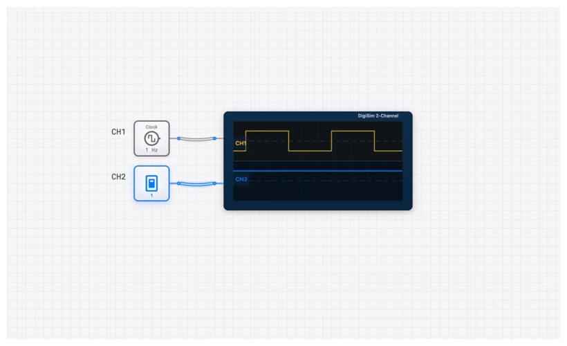
Oscilloscope Verification: Watching the Transitions
In a perfect world, logic gates switch instantaneously. In high-fidelity simulations and real hardware, we must account for propagation delay (). When building high-speed circuits like an ALU_8BIT, these nanoseconds matter.
By connecting an OSCILLOSCOPE to your XNOR inputs and output, you can visualize the “glitches” that occur during switching. If Input A stays HIGH and Input B flips from LOW to HIGH, there is a brief window where the gate is processing the change.
In digisim.io, use the OSCILLOSCOPE_8CH to monitor a 4-bit comparison. You will see that as the inputs change, the “Equal” signal might flicker before settling. This is why synchronous logic (using a CLOCK and D_FLIP_FLOP) is vital — it waits for the XNOR gates to settle before reading the result.
Curriculum Connection
The XNOR gate appears at several critical junctures:
- The XOR Gate — the complement gate that detects difference.
- XOR vs. XNOR: The Critical Difference — the head-to-head comparison for error detection.
- Visualizing Logic: Karnaugh Maps — minimization that frequently produces XNOR-shaped patterns.
- Logic Gate Truth Tables — a single-page reference covering every gate.
Common Pitfalls
- Floating Inputs: Never leave an XNOR input unconnected. In digisim.io, an unconnected input behaves unpredictably. Use a CONSTANT_ZERO if you need to tie an input LOW.
- Confusing XOR and XNOR: In the heat of a complex build, it is easy to grab the wrong gate. XOR is the “Difference” gate (output 1 if inputs differ). XNOR is the “Equality” gate (output 1 if inputs match).
- Chaining Delays: If you chain ten XNOR gates to compare a 10-bit number, the propagation delay accumulates. If your CLOCK is too fast, the output will be sampled before the signal has finished propagating. Always verify timing with the OSCILLOSCOPE_8CH.
- Multi-Input XNOR Misuse: Remember that a cascaded XNOR chain performs even-parity detection, not all-equal detection. To check whether three or more signals are identical, use pairwise XNOR gates fed into an AND gate.
Conclusion: The Equality Checker
The XNOR gate is the equality checker behind every variable comparison, combination lock, and even-parity verification. Build a 4-bit magnitude comparator from XNOR + AND, then extend it to 8 bits and measure propagation delay with the OSCILLOSCOPE.
For the next step in the XOR family, read XOR vs. XNOR: The Critical Difference in Error Detection — the parity-checking comparison. Open the XNOR component reference to start.