The T Flip-Flop: A Toggle Cell for Counters and Timers
The T flip-flop toggles on each clock edge when T=1, making it the canonical building block of frequency dividers, ripple counters, and modulo-N timers.

TL;DR: A T flip-flop toggles its stored bit on every active clock edge when T=1 and holds it when T=0. Its characteristic equation is . Tied permanently to T=1, it divides input frequency by 2; chained, it forms ripple counters and the precision frequency dividers used in quartz watches.
The T_FLIP_FLOP captures one of the most fundamental operations in digital systems: toggle. On each clock edge, if the T input is HIGH the output flips; if LOW, the output holds. From this single rule comes the frequency divider, the ripple counter, and the program counter in every CPU. While the D flip-flop and JK flip-flop get more textbook attention, the T flip-flop is the canonical cell for counting and timing.
What is a T_FLIP_FLOP? The Digital Toggle Switch
The T_FLIP_FLOP is a sequential logic circuit, which is a fancy way of saying it has memory. Unlike a basic AND or OR gate, where the output depends only on what’s happening right now, a T_FLIP_FLOP remembers its previous state. It’s a bistable multivibrator that stores a single bit of information (a 0 or a 1) and only changes its state on a specific clock edge.
Think of it as a disciplined light switch that only flips when someone snaps their fingers—that “snap” is our CLOCK signal. In the hierarchy of digital components, the T_FLIP_FLOP sits squarely in the sequential logic family. While a D_FLIP_FLOP is designed for storing data (Data/Delay) and a JK_FLIP_FLOP is a versatile “jack-of-all-trades,” the T_FLIP_FLOP is specialized for one thing: toggling. This specialization makes it incredibly efficient for building counters and frequency dividers.
Technical Specification: The Rules of the Toggle
The behavior of a T_FLIP_FLOP is governed by its T input at the moment of a rising clock edge. Its truth table is the most straightforward of all flip-flops, which is why it makes a good starting point when moving from combinational to sequential logic.
| T Input | Current State () | Next State () | Action |
|---|---|---|---|
| 0 | 0 | 0 | Hold |
| 0 | 1 | 1 | Hold |
| 1 | 0 | 1 | Toggle |
| 1 | 1 | 0 | Toggle |
As you can see, when T is 0, the output holds its value. When T is 1, inverts. This simple rule is all you need to know to start designing.
The Boolean Foundation
The behavior can be described with a characteristic Boolean expression using the XOR operation. If you think about it, XOR is the perfect mathematical representation of a toggle: it returns true only when the inputs are different.
The characteristic equation is:
This can also be expanded into its fundamental gate form:
Let’s break that down for a second. If , the equation simplifies to . The output inverts. If , it simplifies to . The output remains the same. It’s mathematically elegant and practically bulletproof.
I chose the Component Circuit link here because it provides the cleanest environment to verify the truth table without any external circuit noise.
Common Pitfall: Timing and Edge Triggering
When a counter “glitches,” the culprit is usually timing rather than the logic itself. See The Unseen Clock for setup/hold and metastability.
A common point of confusion is the difference between a latch and a flip-flop. If a T-type circuit were level-triggered (like a latch), setting would cause the output to oscillate uncontrollably for as long as the CLOCK signal was high. The output would flip, which would then be fed back, causing it to flip again, and again, as fast as the gates could move. This is a classic race-around condition.
This is precisely why the T_FLIP_FLOP in digisim.io is edge-triggered. It only pays attention to its T input at the exact instant the CLOCK signal transitions from low to high (the rising edge). This discrete sampling moment prevents chaotic oscillation and ensures a clean, predictable toggle once per clock cycle.
When you’re debugging in the simulator, keep an eye on your propagation delays (). If your T input changes at the exact same nanosecond as your clock edge, you might hit a setup or hold time violation. In the real world, this leads to metastability; in digisim.io, it’s a reminder to always ensure your data is stable before the clock hits.
Application 1: The Frequency Divider
The most direct and important application of a T_FLIP_FLOP is as a frequency divider. If you permanently tie the T input to a HIGH signal (using a CONSTANT component), the flip-flop will toggle its output on every single rising edge of the clock.
The mathematics are straightforward. Let be the input clock frequency. On each rising edge, Q inverts:
- Edge 1: Q goes from 0 to 1 (rising edge of output)
- Edge 2: Q goes from 1 to 0 (falling edge of output)
It takes two input edges to produce one complete output cycle. Therefore:
Chain T Flip-Flops in series (each one’s Q output driving the next one’s clock input), and you get:
This exponential division is why the T Flip-Flop is central to timing circuits. A single chain of 15 flip-flops can divide a 32,768 Hz crystal oscillator down to exactly 1 Hz—the principle behind every quartz watch.

Open Frequency Divider Template
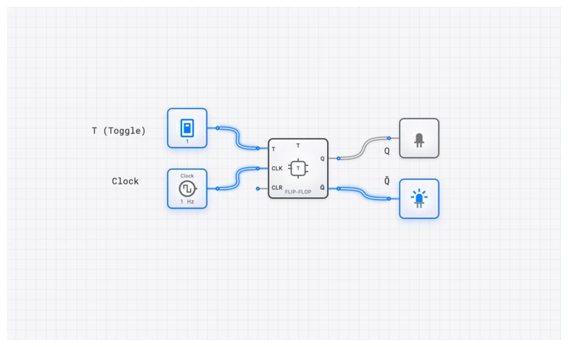
Verifying with the OSCILLOSCOPE
To verify the divide-by-2 behavior directly, use the OSCILLOSCOPE tool in digisim.io.
- Place a CLOCK and a T_FLIP_FLOP.
- Connect a CONSTANT (set to 1) to the T input.
- Connect the CLOCK output to the T_FLIP_FLOP’s clock input.
- Add an OSCILLOSCOPE and connect Channel 1 to the CLOCK and Channel 2 to the output.
When you run the simulation, you’ll see the waveforms side-by-side. The waveform will be exactly twice as “wide” as the clock waveform. You’ve just built the most fundamental timing circuit in digital electronics.
Application 2: The Asynchronous Ripple Counter
What happens if you chain these frequency dividers together? You get a binary counter. This is where the T_FLIP_FLOP really shines. Imagine you have four T_FLIP_FLOP components.
- The main CLOCK drives the first flip-flop (FF0). Its output, , is the Least Significant Bit (LSB).
- The output is then used as the clock input for the next flip-flop (FF1).
- This continues down the line.
This creates a “ripple” effect. When flips from 1 to 0, it creates a falling edge. If we trigger our flip-flops on the falling edge (or use an inverter), that transition triggers FF1 to toggle. When FF1 flips from 1 to 0, it triggers FF2, and so on. The outputs will sequence through binary numbers: 0000, 0001, 0010… all the way to 1111.
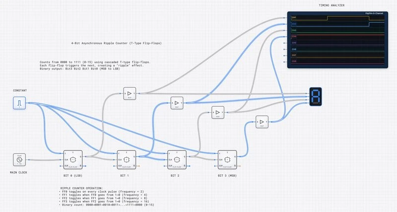
This is called an asynchronous or “ripple” counter because the clock signal isn’t shared; it ripples through the chain. While ripple counters have a slight delay between bits (which you can see beautifully using a SimCast animation at slow speeds), they are incredibly simple to design.
To debug a multi-bit counter like this, the OSCILLOSCOPE_8CH is your best friend. By connecting each output to a separate channel, you can see the entire binary sequence unfold over time and spot the tiny propagation delays that characterize ripple logic.
Real-World Applications: From Atari to Quartz
This isn’t just academic theory. The T_FLIP_FLOP logic is embedded in the history of computing.
1. Vintage Video Game Consoles
Early consoles like the Atari 2600 didn’t have the luxury of high-speed gigahertz processors. They relied on custom chips like the TIA (Television Interface Adaptor). The TIA used chains of flip-flop counters to keep track of where the electron beam was on the TV screen. By using T-type toggle logic to divide the master clock, the chip could precisely trigger the “Horizontal Sync” and “Vertical Sync” signals required to draw an image on a CRT monitor.
2. Quartz Watches and Clocks
Ever wonder why quartz watches are so accurate? They use a tiny quartz crystal that vibrates at exactly 32,768 Hz. Why that specific number? Because . Inside the watch, a chain of 15 T_FLIP_FLOPs acts as a frequency divider. Each stage cuts the frequency in half: 32,768 16,384 8,192… after 15 stages, you get exactly 1 Hz. That 1 Hz pulse is what moves the second hand exactly once per second.
3. Industrial Event Counters
In a factory setting, a simple proximity sensor might detect bottles moving down a conveyor belt. Each time a bottle passes, the sensor sends a pulse. This pulse can be fed directly into the clock input of a T_FLIP_FLOP chain. This creates a robust, hardware-based counter that doesn’t need a complex microprocessor or software to track inventory.
Related Lessons in the digisim.io Curriculum
- The D Flip-Flop — the essential primer on memory and edge-triggering.
- The JK Flip-Flop — the universal cell that includes toggle as one of four modes.
- Counters and State Machines — using flip-flop chains for complex sequencing.
- Mastering Frequency Division — extending toggling into modulo-N counters.
Your Challenge: Put Theory into Practice
Three exercises:
- The Divide-by-8 Challenge: Build a circuit that takes a 1kHz clock and outputs a 125Hz square wave using only T_FLIP_FLOP components.
- The Hybrid Design: Build a T_FLIP_FLOP using a D_FLIP_FLOP and an XOR gate. (Hint: .)
- The Decade Counter: Take the 4-bit ripple counter and add a single NAND gate to make it a Decade Counter (0-9). Detect the binary state for 10 () and route it to the reset pins.
Open the T_FLIP_FLOP component reference to verify the truth table directly.