The Half Adder: Your First Step into Digital Logic Design
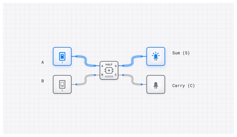
A half adder uses an XOR gate for the Sum and an AND gate for the Carry to add two single bits — the foundational atom of all binary arithmetic.

TL;DR: A half adder is the simplest binary-addition circuit. Two inputs (A, B) produce two outputs: Sum = (XOR) and Carry = (AND). It’s only “half” an adder because it can’t accept a carry-in from a previous column — that requires the full adder.
Every digital computation, from rendering a video frame to calculating a spacecraft’s trajectory, ultimately reduces to a cascade of binary decisions. The simplest non-trivial example is the HALF_ADDER — two gates that show how a machine “knows” that . The construction is foundational because every multi-bit adder, every ALU, and every CPU arithmetic path starts from this circuit.
Defining the HALF_ADDER
A HALF_ADDER is a combinational logic circuit designed to perform the addition of two single binary digits. In the hierarchy of digital systems, it sits just above basic logic gates but below the more complex FULL_ADDER and ALU (Arithmetic Logic Unit). It’s the digital equivalent of adding two numbers in the rightmost column when you do long addition on paper.
The circuit takes two inputs, typically labeled and , and produces two distinct outputs:
- Sum (): The result of the addition in the current bit position.
- Carry (): The “carry-the-one” bit that is passed to the next, more significant column in a multi-bit addition.
To understand why we need two outputs, we only need to look at the four fundamental rules of binary addition:
- (Sum = 0, Carry = 0)
- (Sum = 1, Carry = 0)
- (Sum = 1, Carry = 0)
- (Sum = 0, Carry = 1)
The HALF_ADDER’s entire existence is dedicated to implementing these four rules in hardware. It’s the simplest possible way to handle the “overflow” that occurs when two high signals meet.
The Truth Table: Revealing the Logic
In digital design, we don’t guess; we map. To translate mathematical rules into a physical circuit, we use a truth table. This table exhaustively lists every possible input combination and the required output.
| Input A | Input B | Sum (S) | Carry (C) |
|---|---|---|---|
| 0 | 0 | 0 | 0 |
| 0 | 1 | 1 | 0 |
| 1 | 0 | 1 | 0 |
| 1 | 1 | 0 | 1 |
Look closely at those output columns. If you’ve spent any time with basic logic gates, these patterns should jump off the screen at you.
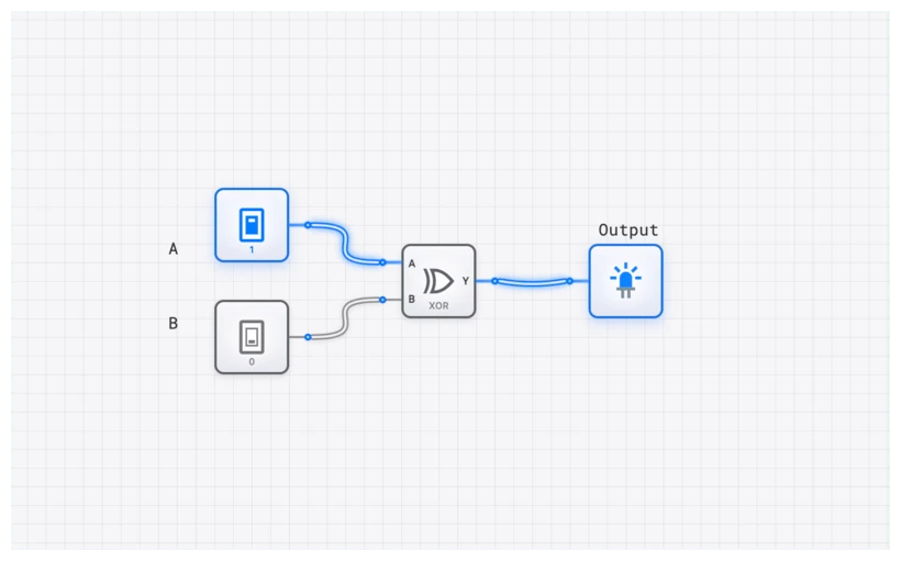
The Sum (S) column is HIGH only when the inputs are different. If both are LOW or both are HIGH, the Sum is LOW. This is the exact definition of an XOR gate: it outputs 1 when the inputs differ and 0 when they match.
The Carry (C) column is HIGH only when both inputs are HIGH. This is the unmistakable signature of an AND gate: it outputs 1 only when every input is 1.
The Boolean Expression
With the gate identities revealed, we can formalize the HALF_ADDER using Boolean algebra. These equations are the “source code” of the hardware world.
For the Sum output, we use the XOR operator, denoted by :
For the Carry output, we use the AND operator, represented by a dot ():
This is the key insight of the half adder. We started with four rules of binary addition, organized them into a truth table, and discovered that the resulting output patterns map directly onto two elementary logic gates: one XOR and one AND. The truth table tells us which gates to use. No guesswork, just systematic pattern recognition—the fundamental method of digital design.
Why is it Only “Half” an Adder?
A common mistake is trying to chain four HALF_ADDER components together to make a 4-bit adder. It won’t work. The HALF_ADDER has a critical limitation: it has no input for a carry-in bit.
Think back to primary school math. If you’re adding , you start at the right: . You write down the and carry the . Now, look at the next column. You aren’t just adding ; you’re adding .
That second column requires three inputs. A HALF_ADDER only has two ( and ). It can handle the very first column of an addition (the Least Significant Bit), but it’s useless for any subsequent columns because it can’t “listen” to the carry bit coming from the previous stage.
To build a real-world multi-bit adder, you need a FULL_ADDER, which adds a third input (). We call this the “Half” adder because it only does half the job required for multi-bit arithmetic.
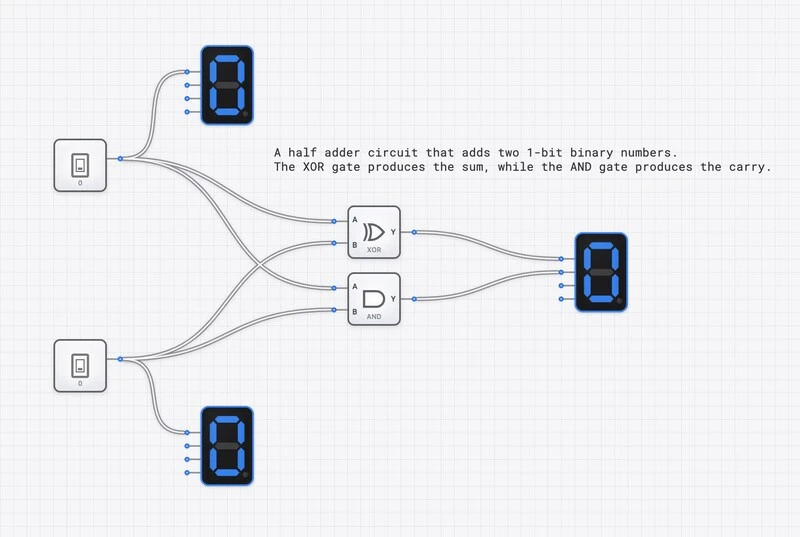
Building the Circuit on digisim.io
Let’s move from theory to implementation. Building a HALF_ADDER from discrete gates is a rite of passage. Follow these steps in the digisim.io editor:
- Place Inputs: Drag two INPUT_SWITCH components onto the canvas. Label them
AandB. - Place Logic: Add one XOR gate and one AND gate.
- Place Outputs: Add two OUTPUT_LIGHT components. Label them
SumandCarry. - Wiring:
- Connect
Input Ato the first input of the XOR and the first input of the AND. - Connect
Input Bto the second input of the XOR and the second input of the AND. - Connect the XOR output to the
Sumlight. - Connect the AND output to the
Carrylight.
Visualizing with SimCast
When you toggle the switches, you’ll see the signals propagate. In a SimCast animation, you can actually observe the slight delay as the signal travels through the XOR gate versus the AND gate. While they appear instantaneous to the human eye, in high-speed computing, these nanoseconds matter.
Verification with the OSCILLOSCOPE
To truly understand the behavior of your circuit, especially as you move toward more advanced topics and beyond, you need to look at the timing.
Place an OSCILLOSCOPE_8CH into your circuit. Connect Channel 1 to Input A, Channel 2 to Input B, Channel 3 to Sum, and Channel 4 to Carry.
As you toggle the switches, the OSCILLOSCOPE will show you the logic levels over time. You’ll notice that the Carry only spikes when both input channels are at (Logic 1). This real-time waveform analysis is how professional engineers debug “glitches”—brief, unwanted transitions in the output that occur because different gates have different propagation delays ().
In a HALF_ADDER, the XOR gate is typically more complex and slightly slower than the AND gate. On the OSCILLOSCOPE, you might see the Sum bit change a fraction of a microsecond after the Carry bit when transitioning from to .
Real-World Applications
The HALF_ADDER isn’t just a classroom example; it’s a workhorse in industry.
1. The LSB of the ALU
In every Arithmetic Logic Unit (ALU), from the classic MOS 6502 to the latest Apple M3 chip, multi-bit addition starts with a HALF_ADDER. Because the Least Significant Bit (LSB) has no bit to its right, there is never a carry-in to worry about. Using a HALF_ADDER here instead of a FULL_ADDER saves transistors, reduces heat, and increases speed.
2. Address Generation Units (AGUs)
Processors spend a lot of time calculating memory addresses. Often, this involves simply incrementing a value (adding 1). A simple incrementer can be built by feeding a signal into a chain of adders. The very first stage of that incrementer is almost always a HALF_ADDER.
Moving Forward in the Curriculum
The HALF_ADDER is your gateway to digital arithmetic. Once you’ve mastered this, you’re ready for the following:
- Half Adder vs. Full Adder: handling that pesky carry-in bit.
- Mastering Binary Addition: Building a 4-Bit Ripple Carry Adder: stringing adders into multi-bit arithmetic.
- Mastering Boolean Algebra: the language used to derive these expressions.
Final Thoughts
The HALF_ADDER takes the messy, human concept of “addition” and reduces it to two elegant logic gates: XOR for Sum and AND for Carry.
The next post in this series, The Half Adder vs. The Full Adder, shows how to extend this circuit to accept carry-in and chain it across multiple bits. Open the HALF_ADDER component reference to verify the truth table directly.