The Half Adder vs. The Full Adder: How Computers Do Math
Half adders sum two bits and produce a carry; full adders sum three bits (including carry-in). Chain full adders to build multi-bit ripple-carry adders.

TL;DR: A half adder sums two single bits to produce Sum (XOR) and Carry (AND). A full adder sums three bits — A, B, and a carry-in — and is the cell you chain into a ripple-carry adder. The full adder is what every column of binary addition above the LSB needs, because each column receives a carry from the column below.
Every calculation a computer performs ultimately reduces to adding binary numbers. The two foundational circuits that make this possible are the half adder and the full adder. This post compares them side-by-side and chains them into a multi-bit adder.
Binary Addition: The Foundation
Before diving into circuits, let’s understand how binary addition works. In binary, we only have two digits: 0 and 1. Addition follows these simple rules:
- 0 + 0 = 0 (no sum, no carry)
- 0 + 1 = 1 (sum of 1, no carry)
- 1 + 0 = 1 (sum of 1, no carry)
- 1 + 1 = 10 (sum of 0, carry of 1)
That last case is crucial: 1 + 1 = 10 in binary (which equals 2 in decimal). Just like in decimal addition when 5 + 5 = 10, we get a “carry” to the next column.
The Half Adder
A half adder is the simplest arithmetic circuit. It adds two single bits and produces two outputs: a Sum and a Carry.
Half Adder: Two Inputs, Two Outputs
Inputs: A, B (the two bits to add)
Outputs: Sum (S), Carry (C)
Boolean Expressions:
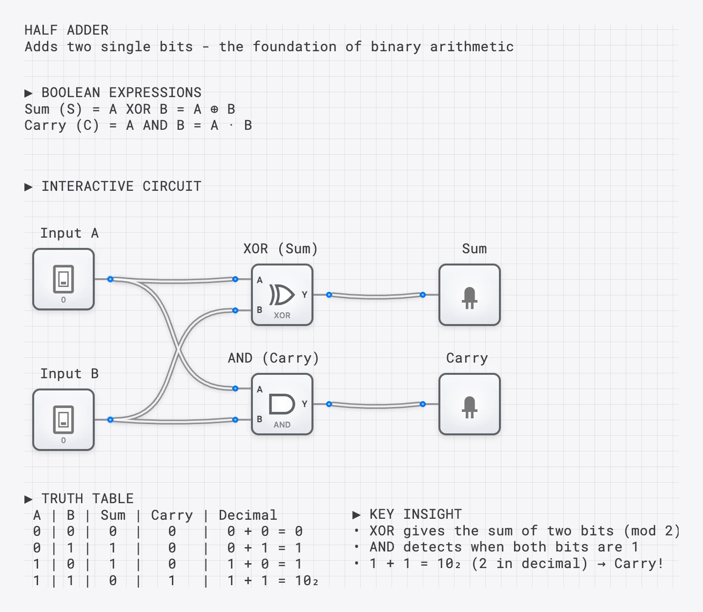
A half adder circuit: XOR gate produces the Sum, AND gate produces the Carry. The truth table shows all input combinations.
| A | B | Sum (A⊕B) | Carry (A·B) | Result (Decimal) |
|---|---|---|---|---|
| 0 | 0 | 0 | 0 | 0 + 0 = 0 |
| 0 | 1 | 1 | 0 | 0 + 1 = 1 |
| 1 | 0 | 1 | 0 | 1 + 0 = 1 |
| 1 | 1 | 0 | 1 | 1 + 1 = 2 (10₂) |
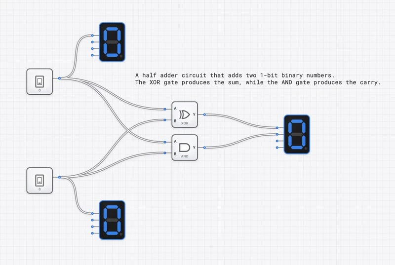
Interactive Half Adder template showing inputs on digit displays and the Sum/Carry outputs.
Key Insight: Why XOR for Sum?
The XOR gate is perfect for the sum bit because it outputs 1 only when the inputs are different. For 1+1, XOR gives 0 (the sum digit of “10”), while AND gives 1 (the carry digit). XOR essentially gives you the remainder when dividing by 2!
The Half Adder’s Limitation
Why is it called a “half” adder? Because it can only add two bits—it has no input for a carry from a previous addition. When adding multi-bit numbers, you need to handle carries from one column to the next.
Consider adding 11 + 01 in binary (3 + 1 = 4):
  1 1   (3 in decimal)
+ 0 1   (1 in decimal)
-----
  ?
The rightmost column (1+1) produces Sum=0 and Carry=1. That carry must be added into the next column along with the 1 and 0 already there. A half adder has only two inputs, so it cannot accept this third value—we need a full adder.
The Full Adder
A full adder adds three bits: A, B, and a Carry In (Cin) from a previous stage. It outputs a Sum and a Carry Out (Cout).
Full Adder: Three Inputs, Two Outputs
Inputs: A, B, Carry In (Cin)
Outputs: Sum (S), Carry Out (Cout)
Boolean Expressions:
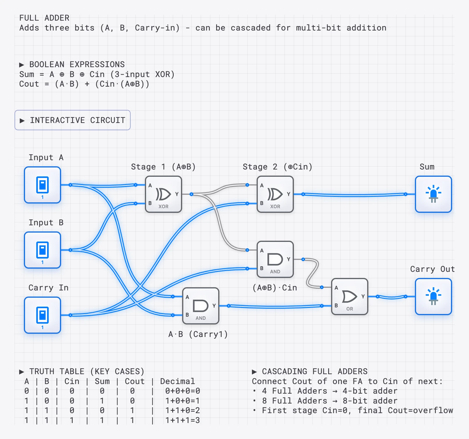
The Full Adder: built from two half adders and an OR gate. Each half adder handles one level of addition.
| A | B | Cin | Sum | Cout | Total |
|---|---|---|---|---|---|
| 0 | 0 | 0 | 0 | 0 | 0 |
| 0 | 0 | 1 | 1 | 0 | 1 |
| 0 | 1 | 0 | 1 | 0 | 1 |
| 0 | 1 | 1 | 0 | 1 | 2 |
| 1 | 0 | 0 | 1 | 0 | 1 |
| 1 | 0 | 1 | 0 | 1 | 2 |
| 1 | 1 | 0 | 0 | 1 | 2 |
| 1 | 1 | 1 | 1 | 1 | 3 |
Full Adder template showing carry propagation from half adders through an OR gate.
Half Adder vs. Full Adder Comparison
| Feature | Half Adder | Full Adder |
|---|---|---|
| Inputs | 2 (A, B) | 3 (A, B, Cin) |
| Outputs | 2 (Sum, Carry) | 2 (Sum, Cout) |
| Handles Carry In? | No | Yes |
| Gate Count | 2 (1 XOR, 1 AND) | 5 (2 XOR, 2 AND, 1 OR) |
| Use Case | LSB addition only | Any bit position |
Building a 4-Bit Ripple Carry Adder
Now for the real power: chaining full adders to add multi-bit numbers! A 4-bit ripple carry adder adds two 4-bit numbers by connecting four full adders in series.
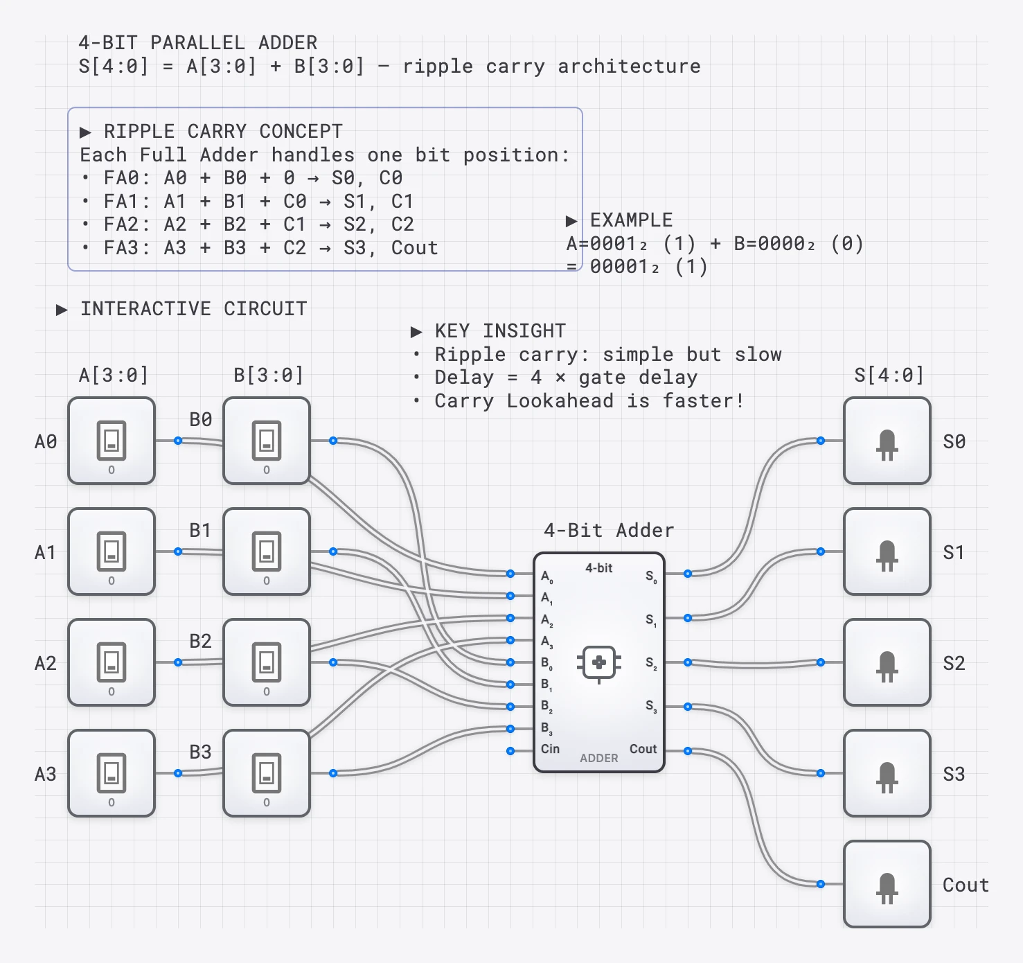
A 4-bit ripple carry adder: the Cout of each full adder connects to the Cin of the next, creating a “ripple” effect.
How it works:
- The first full adder (rightmost) adds A₀ + B₀ with Cin = 0
- Its Cout connects to the Cin of the next adder
- This “carry chain” continues through all 4 bits
- The final Cout indicates overflow (result > 15 for 4 bits)
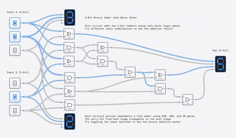
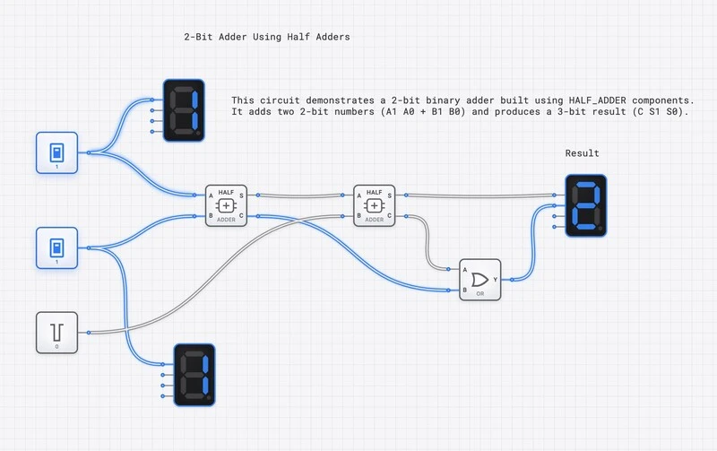
A 3-bit ripple carry adder showing cascaded full adders. The carry “ripples” from right to left.
Key Insight: Ripple Delay
Why “ripple”? Because the carry must propagate through each adder sequentially. The final sum bit is not valid until the carry has “rippled” through every preceding stage. For an N-bit ripple carry adder, the worst-case delay is approximately , where is the propagation delay of a single full adder’s carry path. This linear scaling limits the speed of ripple carry adders, which is why modern CPUs use carry-lookahead adders that compute all carries in parallel.
From Adders to ALU
Adders are the heart of the CPU’s Arithmetic Logic Unit (ALU). By adding control logic, an ALU can:
- Add: A + B (direct addition)
- Subtract: A - B (using two’s complement: A + NOT(B) + 1)
- Compare: Is A > B? (check the result of A - B)
- Increment: A + 1
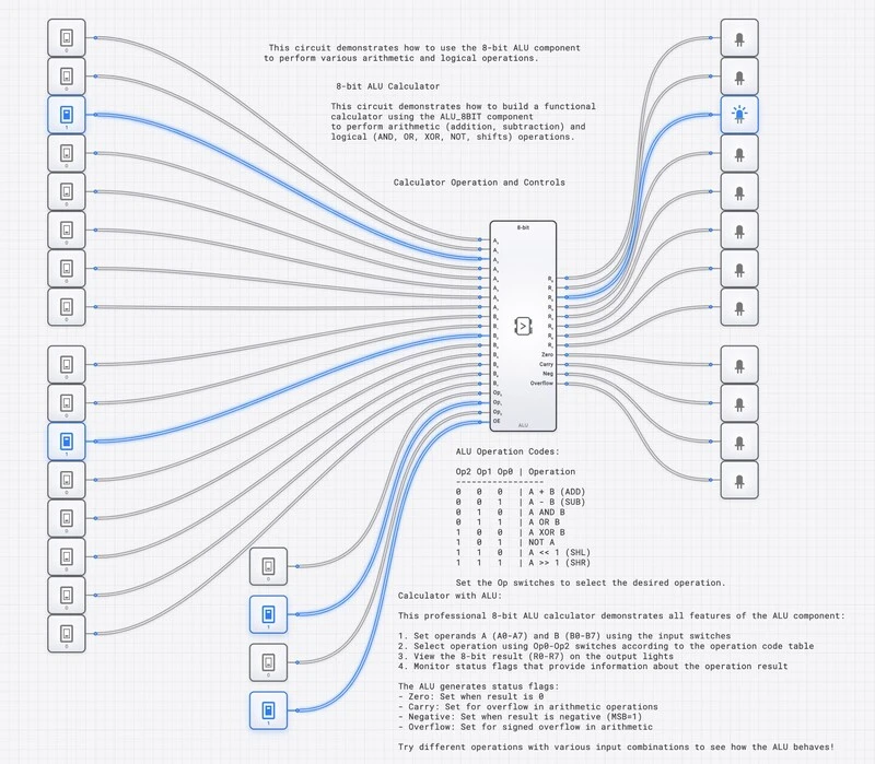
An 8-bit ALU that uses adders for both arithmetic operations (ADD, SUB) and logical operations (AND, OR, XOR).
Try It Yourself!
Build these arithmetic circuits in DigiSim.io:
- Half Adder: Connect an XOR and AND gate to two switches.
- Full Adder: Use two half adders and an OR gate.
- 2-Bit Adder: Chain two full adders together.
- Subtractor: Add inverters and set Cin=1 for subtraction!
For the deeper construction, see The Half Adder: Your First Step into Digital Logic Design and Mastering Binary Addition: Building a 4-Bit Ripple Carry Adder. Open the HALF_ADDER component reference to verify the truth table directly.
digisim.io • Blog • Lessons