In 1703, Gottfried Wilhelm Leibniz published a paper describing a number system that uses only two symbols: 0 and 1. He was not building a computer. He was searching for a universal language of reason, a way to reduce all human thought to mechanical calculation. Three centuries later, every processor on the planet operates in exactly the system he described.
The story of binary is not a story about technology. It is a story about an idea — perhaps the most consequential idea in the history of engineering — that took 250 years to find its machine.
Ancient Roots: Binary Before Electricity
Binary thinking predates Leibniz by millennia. The I Ching, the ancient Chinese divination text dating to roughly 1000 BCE, represents the cosmos through combinations of broken and unbroken lines — yin and yang, 0 and 1. Its sixty-four hexagrams exhaust every possible combination of six binary digits. Leibniz himself acknowledged the I Ching’s influence, seeing in it a confirmation that binary representation is a natural structure, not merely a human invention.
In sub-Saharan Africa, the Bamana people of Mali developed a divination system called geomancy that operates on binary combinations of single and double marks. Researchers have traced binary-structured African mathematical practices back centuries, suggesting that the insight of two-state representation emerged independently across cultures.
These were not engineering projects. They were philosophical frameworks. But they share a critical insight with modern computing: a system of two symbols, combined systematically, can represent anything.
Leibniz and the Dream of Mechanical Reason
Leibniz saw binary as more than a number system. He imagined a calculus ratiocinator — a machine that could resolve disputes by computation. “Let us calculate,” he proposed, suggesting that disagreements could be settled the way arithmetic problems are solved: mechanically, definitively.
His binary arithmetic worked exactly as modern binary does. He showed that addition, subtraction, and multiplication follow the same rules in base 2 as in base 10, just with fewer symbols. His notation:
| Decimal | Binary |
|---|---|
| 0 | 0 |
| 1 | 1 |
| 2 | 10 |
| 3 | 11 |
| 4 | 100 |
| 7 | 111 |
| 10 | 1010 |
Leibniz’s system was mathematically correct but practically useless in his era. Human arithmetic is faster in decimal. Binary only becomes advantageous when the calculator is a machine made of switches that are either open or closed, and no such machine existed in 1703.
Boole’s Algebra of Thought
The next essential piece came from George Boole, a self-taught English mathematician who, in 1854, published An Investigation of the Laws of Thought. Boole formalized logic itself as algebra. He showed that the propositions “it is raining” and “I have an umbrella” could be represented as variables taking values of TRUE or FALSE, combined through operations he called AND, OR, and NOT.
Boole’s key insight: logical reasoning follows mathematical laws. If represents “it is raining” and represents “I have an umbrella,” then:
- means both conditions are true.
- means at least one condition is true.
- means “it is not raining.”
These operations obey precise algebraic rules:
Boole never built a circuit. He was formalizing the structure of human reasoning. But he had, without knowing it, written the instruction manual for every digital computer that would ever be built.
Shannon’s Bridge: From Logic to Circuits
For eighty years, Boolean algebra remained a tool of philosophers and logicians. Then, in 1937, a 21-year-old MIT graduate student named Claude Shannon submitted what is arguably the most important master’s thesis of the twentieth century: A Symbolic Analysis of Relay and Switching Circuits.
Shannon’s observation was disarmingly simple. He noticed that electrical relays — switches that are either open (0) or closed (1) — obey the same rules as Boolean algebra. A circuit with two switches in series implements AND: current flows only when both switches are closed. A circuit with two switches in parallel implements OR: current flows when either switch is closed. A normally-closed relay implements NOT: current flows when the control signal is absent.
With this correspondence established, any Boolean expression could be directly translated into a circuit diagram. The abstract algebra of logic became a practical engineering tool. Shannon had bridged the gap between Boole’s mathematics and the physical world of electricity.
Information Theory: Why Binary Is Optimal
Shannon went further. In 1948, he published “A Mathematical Theory of Communication,” founding the field of information theory. He defined the fundamental unit of information as the bit — a single binary digit — and proved that any message can be encoded as a sequence of bits.
Why is one bit the natural unit? Because it represents the resolution of one binary uncertainty. Before you know the value of a bit, it could be 0 or 1 — two possibilities. After you know it, the uncertainty is resolved. Shannon showed that the information content of a message is measured in bits regardless of how the message is physically represented.
This has profound implications. It means binary is not merely a convenient engineering choice — it is the minimal unit of distinction. You cannot encode information with fewer than two states. A system with one state conveys nothing (no uncertainty to resolve). A system with three or more states can always be decomposed into multiple binary decisions. Binary is, in a precise mathematical sense, the atomic level of information.
The Physics of Binary: Why Switches Won
The theoretical elegance of binary would matter little if it were not also the most practical choice for physical implementation. The reason it dominates is simple: reliable two-state devices are vastly easier to build than reliable multi-state devices.
A transistor operates most reliably in two modes: fully conducting (saturated) or fully non-conducting (cutoff). In a 3.3V digital system, any voltage above roughly 2V is interpreted as HIGH, and any voltage below roughly 0.8V is interpreted as LOW. That leaves a margin of more than a volt on either side for noise, temperature variation, and manufacturing imprecision.
If you tried to build a ten-state (decimal) system using the same 3.3V range, each state would occupy only 0.33V. A thermal fluctuation of 0.2V — trivial in electronics — could push a signal from one state to another, corrupting data. Multi-level signaling does exist (it is used in modern NAND flash memory and high-speed serial links), but it requires elaborate error correction and operates with narrower noise margins. For the logic core of a processor, binary remains unchallenged.
From Bits to Meaning: Encoding the World
A single bit distinguishes between two things. A sequence of bits can distinguish between arbitrarily many things. This is the principle behind every encoding scheme in computing:
- Numbers: An 8-bit byte represents integers from 0 to 255. A 64-bit word represents integers up to .
- Text: ASCII assigns each character a 7-bit code (‘A’ = 1000001, ‘a’ = 1100001). Unicode extends this to represent over 140,000 characters from every writing system on Earth.
- Images: Each pixel in a 24-bit color image is encoded as three 8-bit values (red, green, blue), yielding 16.7 million possible colors.
- Sound: A CD samples audio 44,100 times per second, encoding each sample as a 16-bit number, producing a faithful reproduction of the original waveform.
In every case, the continuous, messy reality of the physical world is discretized — quantized into binary — at the point of input. From that moment on, it is processed, stored, and transmitted as patterns of 0s and 1s without any further loss.
Logic Gates: Where Binary Becomes Action
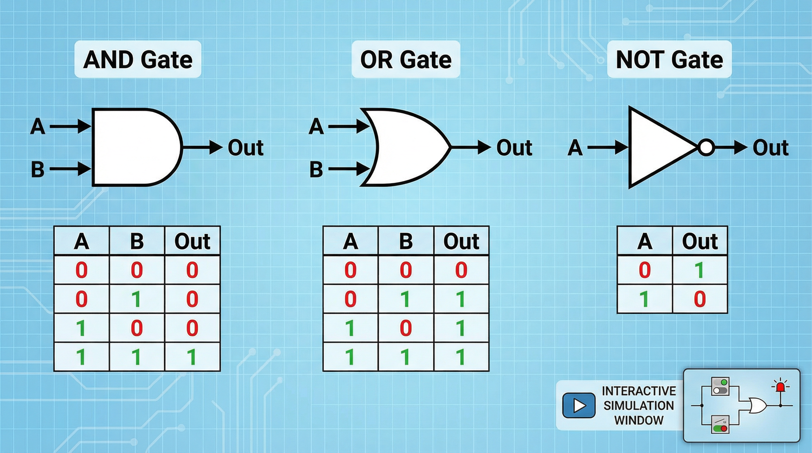
Binary representation gives us a way to encode information. Logic gates give us a way to transform it. The three fundamental gates — AND, OR, and NOT — are the physical embodiment of Boole’s algebra, built from the switches Shannon connected to that algebra in 1937.
| Gate | Rule | Boolean Expression |
|---|---|---|
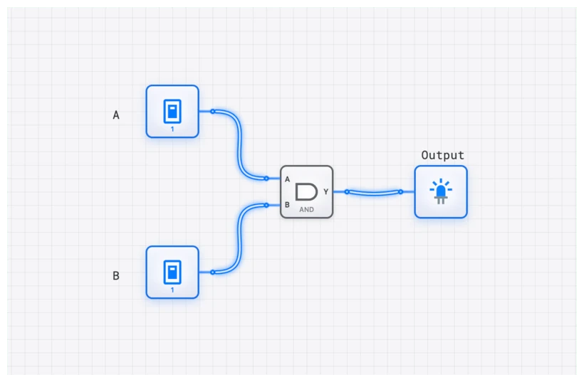
| AND | Output 1 only when all inputs are 1 | |
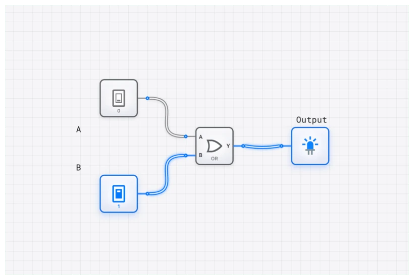
| OR | Output 1 when any input is 1 | |
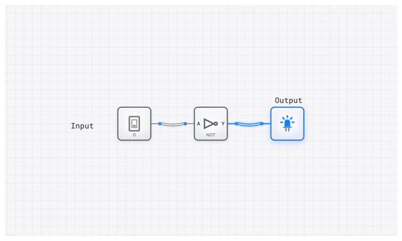
| NOT | Output the opposite of the input |
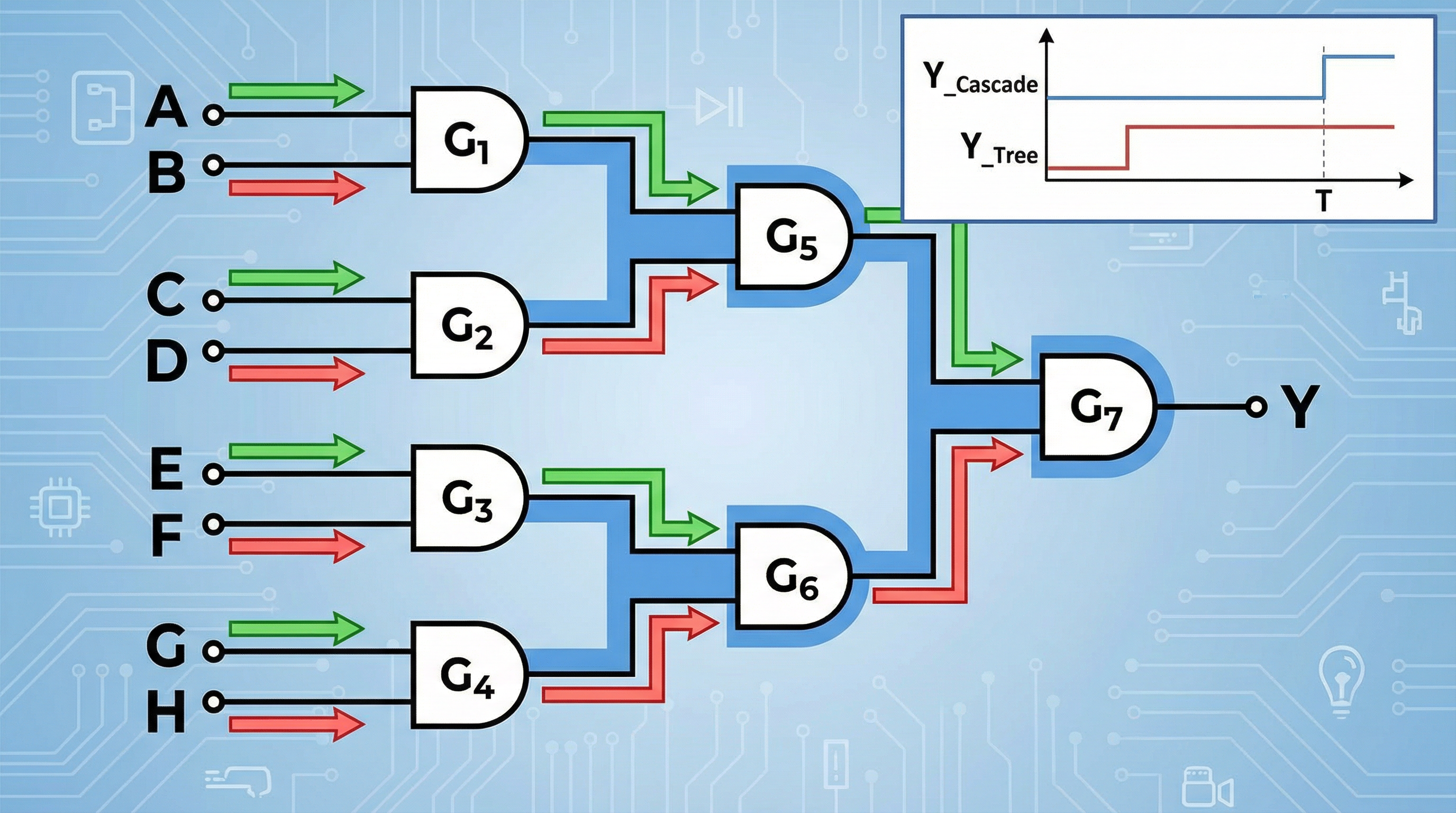
These three operations are functionally complete: any computation that can be expressed as a Boolean function can be built from AND, OR, and NOT gates alone. A modern processor performing floating-point arithmetic, branch prediction, and speculative execution is, at the transistor level, executing vast networks of these three operations billions of times per second.
The Abstraction Ladder: How Binary Scales
The power of binary lies not in the bit itself but in the tower of abstractions built upon it:
- Bits combine into bytes and words to represent numbers, characters, and addresses.
- Logic gates combine bits according to Boolean rules.
- Adders, multiplexers, and comparators combine gates to perform arithmetic and data routing.
- Registers and flip-flops use gates with feedback to store state, creating memory.
- Finite state machines combine memory and logic to implement sequential behavior.
- Processors combine all of the above into a machine that executes instructions.
- Software abstracts the processor into a programmable tool for arbitrary tasks.
Each layer hides the complexity below it. A programmer writing Python does not think about transistors, and a transistor engineer does not think about Python. But the chain is unbroken: the Python interpreter is compiled to machine code, which is executed by a processor, which is a network of gates, which are clusters of transistors, which are switches that are either on or off.
Seeing the Idea in Action
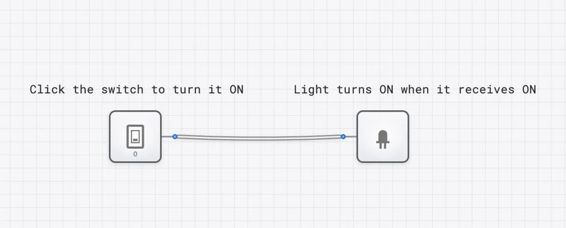
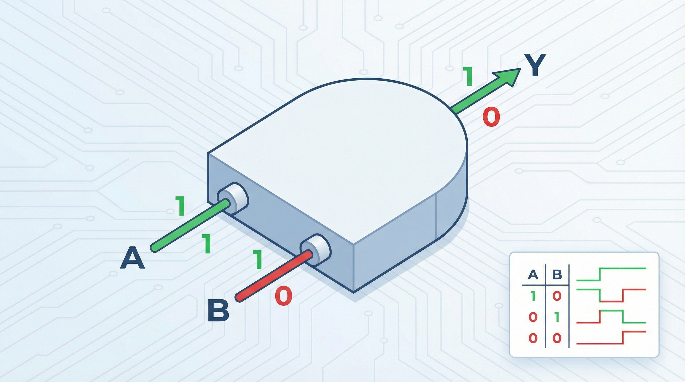
The best way to internalize the binary paradigm is to manipulate it directly. On digisim.io, you can place a switch (Leibniz’s 0 and 1), connect it through a logic gate (Boole’s algebra), and observe the output on a light or oscilloscope (Shannon’s physical realization). In a few clicks, you recapitulate 300 years of intellectual history.
Try this: place two switches and an AND gate. Connect each switch to an input of the gate, and connect the output to a light. Toggle the switches through all four combinations. You are verifying, by direct experiment, the truth table that Boole could only derive on paper. The circuit obeys his algebra because Shannon showed it must.
Binary and the Future: Quantum, Neuromorphic, and Beyond
Binary has dominated computing for nearly a century, but new paradigms are emerging that challenge its monopoly.
Quantum computing replaces the classical bit with the qubit, which can exist in a superposition of 0 and 1 simultaneously. A quantum computer with qubits can represent states at once, enabling certain computations (like factoring large numbers or simulating molecules) to be performed exponentially faster than classical approaches. But quantum computers do not eliminate binary; they extend it. The output of a quantum computation is still measured as classical bits.
Neuromorphic computing mimics biological neurons, which communicate through analog spikes rather than clean digital levels. These systems are promising for pattern recognition and energy-efficient AI, but they typically interface with conventional binary systems for input and output.
Optical computing uses photons instead of electrons, potentially operating at higher speeds and lower power. But the logic is still fundamentally binary: photons are either present or absent, interferometers are constructive or destructive.
In every emerging paradigm, binary remains the interface layer. The encoding of information as discrete 0s and 1s is so fundamental, so mathematically natural, that even radical departures from silicon transistors end up speaking binary at their boundaries.
The Idea That Built a World
Leibniz dreamed of a universal language. Boole formalized the logic. Shannon connected it to electricity. The result is a civilization running on two symbols.
The zeroes and ones are not a limitation. They are a design choice that aligns physics (switches are most reliable in two states), mathematics (Boolean algebra provides a complete logical framework), and information theory (the bit is the irreducible unit of information). When an idea sits at the intersection of three independent lines of reasoning, it is probably correct, and it is probably here to stay.
The circuits you build on digisim.io are a direct continuation of this intellectual lineage. Every AND gate you wire implements Boole’s conjunction. Every switch you toggle is Leibniz’s 0 becoming a 1. Every signal flowing through a wire is Shannon’s insight made tangible.
That is what makes digital logic worth learning. It is not just engineering. It is the point where mathematics becomes physical reality.