Frequency Division: From Flip-Flops to Modulo-N Counters
Frequency division produces a slow clock from a fast one using flip-flops or counters. Build a divider chain, UART baud generator, and PWM timer.

TL;DR: Frequency division turns a fast clock into a slower one. A T flip-flop divides by 2; cascading of them divides by . For arbitrary ratios, a counter plus comparator implements modulo-N division. The same primitive drives digital watches, UART baud generators, and PWM controllers.
Frequency division is behind nearly every digital device. Your digital watch, your microcontroller’s serial port, and the system clock that orchestrates your CPU all depend on dividing a fast clock signal into slower, precisely timed outputs.
This article takes a hands-on approach: build a digital clock divider chain, a UART baud rate generator, and a precision timing circuit on digisim.io. The flip-flop primitive behind every divider is covered in the T flip-flop guide.
Quick Review: The Core Principle
The fundamental equation of frequency division is:
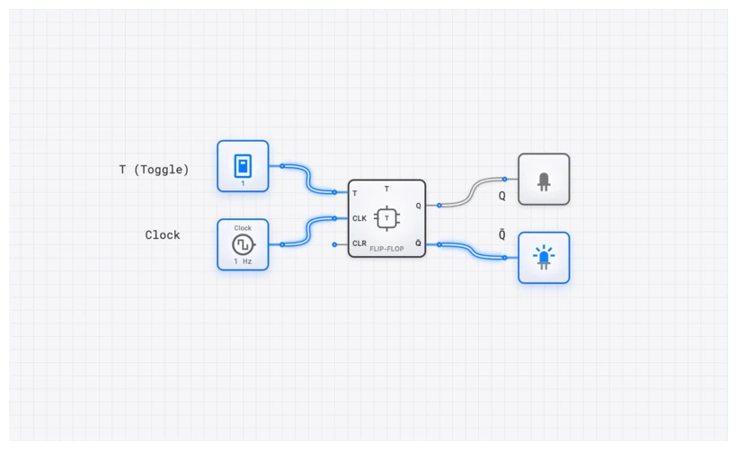
where is the division ratio. A T_FLIP_FLOP with its toggle input held HIGH divides any clock by 2. Cascading flip-flops divides by . For arbitrary (non-power-of-2) division ratios, we use a counter with reset logic: a COUNTER_8BIT counts from 0 to , and a COMPARATOR_8BIT detects when the count reaches and resets the counter to 0.
With that foundation in mind, let us put it to work.
Project 1: Building a Digital Clock Divider Chain
The most classic application of frequency division is the digital clock. Every digital timepiece, from a wristwatch to a wall clock, starts with a quartz crystal oscillating at 32.768 kHz and divides it down to a 1 Hz tick.
Why 32.768 kHz?
The number 32,768 is . This means a chain of exactly 15 divide-by-2 stages (T_FLIP_FLOPs) will produce a perfect 1 Hz output. No modulo-N logic, no comparators, no reset circuits. Just 15 flip-flops in a row:
Building It on digisim.io
While you probably do not want to place 15 individual flip-flops, you can achieve the same result efficiently:
- Place a CLOCK component and set its frequency to represent your crystal oscillator.
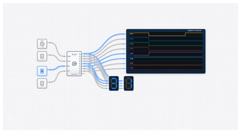
- Place a COUNTER_8BIT. Its Q7 output (the most significant bit) divides the input frequency by 256. This single component handles 8 stages of division.
- Chain a second COUNTER_8BIT by connecting Q7 of the first counter to the clock input of the second. The Q6 output of the second counter now provides division by .
- Connect the output to an OUTPUT_LIGHT. This light will blink at 1 Hz.
Extending to Minutes and Hours
Once you have a 1 Hz signal, building a complete clock requires two more divider stages:
- Seconds to minutes: Divide by 60. Use a COUNTER_8BIT with a COMPARATOR_8BIT set to detect 60. The reset signal feeds back to the counter’s RST input. The carry output (the reset pulse) becomes the “minute tick.”
- Minutes to hours: Another divide-by-60 stage, identical to the first. Its carry output is the “hour tick.”
- Hour counter: A final divide-by-12 (or divide-by-24) stage counts the hours.
Connect each stage’s counter output to a SEVEN_SEGMENT_DISPLAY through a BCD_TO_7SEG decoder, and you have a functioning digital clock.
Project 2: UART Baud Rate Generator
Serial communication is one of the most common uses of frequency division in embedded systems. The UART protocol requires both the transmitter and receiver to agree on a precise clock rate, called the baud rate. Common baud rates include 9600, 19200, 38400, and 115200 bits per second.
The Problem
Most microcontrollers run at clock speeds like 16 MHz, 8 MHz, or 48 MHz. None of these divide evenly into standard baud rates, so a frequency divider must produce the closest possible approximation.
Calculating the Division Ratio
For a 16 MHz system clock and a target baud rate of 9600:
Since must be an integer, we round to 1667. The actual baud rate becomes:
The error is , well within the UART tolerance of approximately 3%.
Oversampling: The 16x Clock
In practice, UART receivers do not sample at the baud rate itself. They typically use a clock that is 16 times the baud rate, sampling the incoming signal at 16 points within each bit period and using majority voting to determine the bit value. This means the divider actually needs to produce:
Building It on digisim.io
- Place a CLOCK at your system frequency.
- Place a COUNTER_8BIT (or chain two for values above 255).
- Place a COMPARATOR_8BIT and set the comparison value to 104 using a CONSTANT component.
- Connect the COMPARATOR’s “A=B” output to the counter’s RST input.
- Tap the reset pulse as your 16x baud rate clock. This pulse occurs every 104 system clock cycles.
- Add a second divide-by-16 stage to generate the actual baud rate for verification.
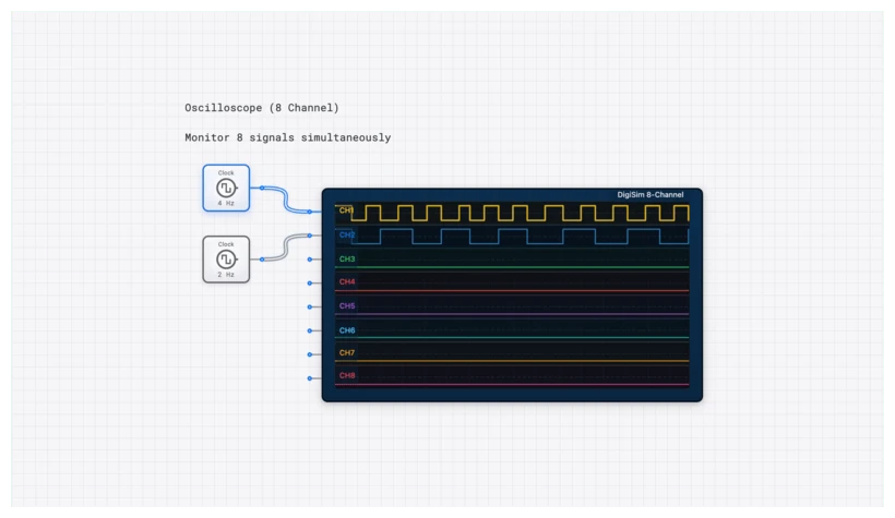
Connect an OSCILLOSCOPE_8CH to the system clock, the 16x clock, and the baud rate clock to visually confirm the timing relationships.
Project 3: Precision Timing for Embedded Systems
Many embedded applications need precise timing intervals that do not correspond to simple power-of-2 divisions. Examples include:
- PWM (Pulse Width Modulation): Controlling motor speed or LED brightness by varying the duty cycle of a signal.
- Sensor sampling: Reading a temperature sensor exactly 100 times per second.
- Display refresh: Updating an LED matrix at a consistent 60 Hz.
Building a Configurable Timer
A versatile timer combines a counter, a comparator, and a register that holds the target count value. By changing the value in the register, you change the output frequency without modifying any wiring.
- Counter: A COUNTER_8BIT counts up from 0 on each system clock tick.
- Match register: A set of INPUT_SWITCH components (or a CONSTANT) specifies the target count value .
- Comparator: A COMPARATOR_8BIT compares the counter’s current value to .
- Reset and output: When the counter reaches , the comparator’s output resets the counter and simultaneously produces a pulse on the timer output line.
This is exactly how hardware timers work in microcontrollers like the ATmega328P (used in Arduino Uno). The timer/counter peripheral has a configurable “output compare” register. When the count matches the register value, an interrupt fires or an output pin toggles.
Generating PWM
To produce a PWM signal:
- Use the counter as a free-running sawtooth generator (counting from 0 to a maximum value, then resetting).
- Use one comparator to set the period (the total count before reset).
- Use a second comparator to set the duty cycle (the count at which the output transitions from HIGH to LOW).
For a counter running at 1 MHz with a period of 1000 and a duty cycle value of 250, you get a 1 kHz signal that is HIGH for 25% of each cycle.
Open Frequency Divider Template
Common Pitfalls in Practice
1. Integer Rounding Errors
When the desired division ratio is not an integer, rounding introduces a frequency error. For critical applications like UART, always calculate the actual output frequency after rounding and verify the error is within tolerance. For audio or RF applications where even small errors are audible or cause signal drift, fractional-N dividers (which alternate between two integer division ratios) are used to achieve non-integer average division.
2. Glitch on Reset
When a modulo-N counter resets, there is a brief moment (one propagation delay) where the counter holds the value before snapping back to 0. In most designs this glitch is invisible to synchronous downstream logic, but if you are feeding the counter output directly to asynchronous circuits, it can cause problems. The solution is to register (latch) the output with a D_FLIP_FLOP synchronized to the system clock.
3. Clock Domain Crossing
When a divided clock drives logic in a different clock domain from the original, you must use proper synchronization (typically a chain of two D flip-flops) to avoid metastability. This is a topic for advanced timing analysis, but being aware of it early will save you significant debugging time later.
Verification with the Oscilloscope
For any frequency divider project, the OSCILLOSCOPE_8CH is indispensable:
- Channel 1: Input clock (reference).
- Channel 2: Counter Q0 output (divide-by-2).
- Channel 3: Comparator reset pulse (your divided output).
- Channel 4: Downstream output (e.g., the UART baud clock).
Compare the waveform periods visually. Count the number of input clock edges between successive output pulses to confirm the division ratio. If you use the SimCast feature, you can step through each clock cycle and watch the counter increment, the comparator evaluate, and the reset fire in slow motion.
Project 4: Multiplexed 7-Segment Display Driver
A practical application that combines frequency division with display logic is the multiplexed display. Instead of using a separate decoder for each digit of a multi-digit display, you use a single decoder that cycles through each digit position rapidly.
How It Works
- A fast clock (divided from the system clock to approximately 1 kHz) drives a 2-bit counter.
- The counter selects which digit position is currently active via a 2-to-4 decoder that enables one digit at a time.
- A 4-to-1 MUX routes the BCD value for the active digit to the shared 7-segment decoder.
- The decoder drives the segment lines, which are shared across all digit positions.
Because the counter cycles through all four digit positions every 4 ms (at 1 kHz), human persistence of vision perceives all digits as being continuously lit. This technique reduces the segment driver count from to just lines.
Building It on digisim.io
- Use a CLOCK divided down to approximately 1 kHz.
- Feed it into a 2-bit COUNTER.
- Connect the counter to a 2-to-4 decoder (digit enable) and a 4-to-1 MUX (BCD value selection).
- Wire the MUX output through a BCD_TO_7SEG decoder to a SEVEN_SEGMENT_DISPLAY.
This project ties together frequency division, multiplexing, and decoding into a single cohesive system, demonstrating how these fundamental building blocks compose into real-world circuits.
Summary Table: Common Division Ratios
| Application | Input Frequency | Target Output | Division Ratio () | Method |
|---|---|---|---|---|
| Digital clock (seconds) | 32.768 kHz | 1 Hz | 32768 | 15-stage binary counter |
| Seconds to minutes | 1 Hz | 1/60 Hz | 60 | Mod-60 counter |
| UART 9600 baud (16x) | 16 MHz | 153.6 kHz | 104 | Mod-104 counter |
| Display multiplex | 16 MHz | 1 kHz | 16000 | Cascaded mod-N counters |
| PWM at 1 kHz | 1 MHz | 1 kHz | 1000 | Mod-1000 counter |
| Audio sample rate | 48 MHz | 44.1 kHz | 1088 | Mod-1088 counter |
From Theory to Practice
Frequency division is one of those fundamental skills where the gap between “understanding the concept” and “building a working circuit” is where real learning happens. The four projects above cover the most common use cases you will encounter in digital design:
- The digital clock teaches you power-of-2 division and cascading counters.
- The baud rate generator teaches you arbitrary modulo-N division and error analysis.
- The configurable timer teaches you how to build reusable, parameterized timing circuits.
- The multiplexed display teaches you how frequency division integrates with data routing and decoding.
Each of these projects maps directly to real hardware peripherals found in commercial microcontrollers and FPGAs. Build them on digisim.io, verify them with the oscilloscope, and you will have a solid, practical understanding of clock management that transfers directly to professional design work.
Continue with counters and state machines to add conditional control to your divider, or open the T flip-flop component reference to inspect the toggle primitive itself. For more on the underlying clock signal, see the clock pulse — why computers need a heartbeat.