How does a 5 GHz processor in your laptop communicate with a keyboard that sends data thousands of times slower? The answer isn’t magic; it’s one of the most fundamental and elegant concepts in digital electronics: frequency division. This process acts as a digital gearbox, stepping down high-speed signals to generate the slower, synchronized clocks that orchestrate everything from timekeeping in your watch to data transfer over a USB port.
Without frequency dividers, modern computing would be impossible. Every complex chip is a symphony of components running at different speeds, all perfectly timed and derived from a single, high-frequency master clock. Understanding how to divide a clock signal is not just an academic exercise—it’s a foundational skill for anyone serious about digital design.
What is a Frequency Divider?
At its heart, a frequency divider is a circuit that takes a periodic input signal of frequency and produces an output signal of frequency , where the output frequency is a fraction of the input. The relationship is elegantly simple:
Here, is the division ratio (also called the modulus). If you have a 10 MHz clock and need a 1 MHz signal, you need a frequency divider with . If you need to generate a 1 Hz “tick” for a clock from a 32.768 kHz crystal, you need a divider with .
Equivalently, the output period is times the input period:
Think of it as a turnstile that only lets every Nth person through. For every input clock cycles, exactly one output cycle is produced.
The Fundamental Building Block: The Divide-by-2 Circuit
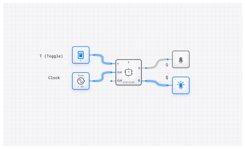
The simplest and most common frequency divider is the divide-by-2 circuit. Its implementation is beautifully minimalistic: a single T_FLIP_FLOP.
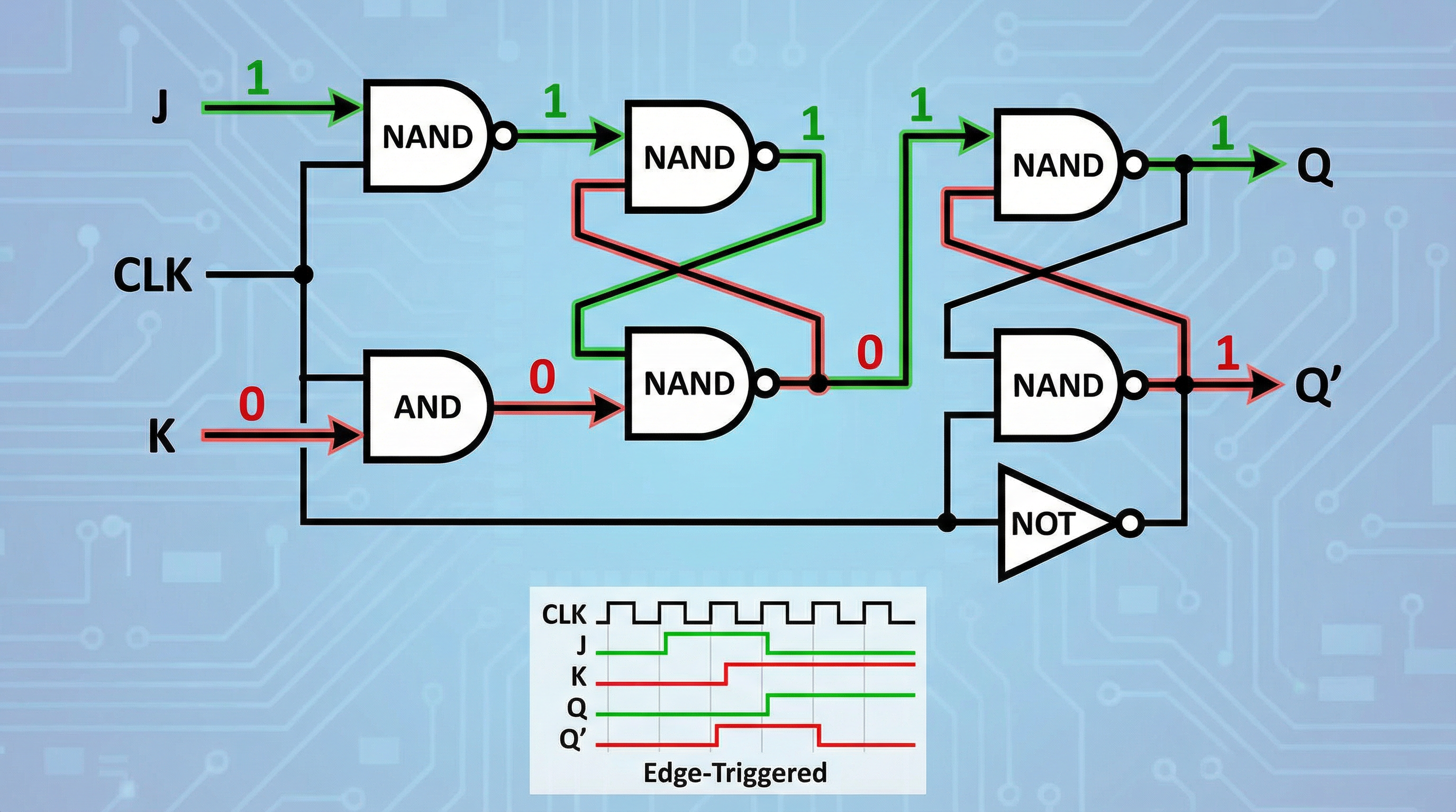
A T_FLIP_FLOP (Toggle Flip-Flop) is a sequential logic element that changes its output state on every active clock edge (typically the rising edge) if its ‘T’ (Toggle) input is held HIGH. If you feed a clock signal into its CLK input and tie the T input to a HIGH signal (a CONSTANT ‘1’), the output Q will flip from 0 to 1, then 1 to 0, on each successive clock pulse.
Because the output only completes a full cycle (0 -> 1 -> 0) for every two input clock cycles (0 -> 1, 1 -> 0), its frequency is exactly half of the input clock’s frequency.
You can easily construct a T_FLIP_FLOP from a D_FLIP_FLOP by connecting its inverted output, , back to its D input. This creates a feedback loop where the flip-flop’s next state is always the opposite of its current state, forcing it to toggle.
I’ve set up a simple template circuit for you to see this in action. It includes a CLOCK, a T_FLIP_FLOP, and an OSCILLOSCOPE to visualize the result. Notice how the output waveform is exactly twice as wide as the input clock’s waveform.
Power-of-2 Division with Counters
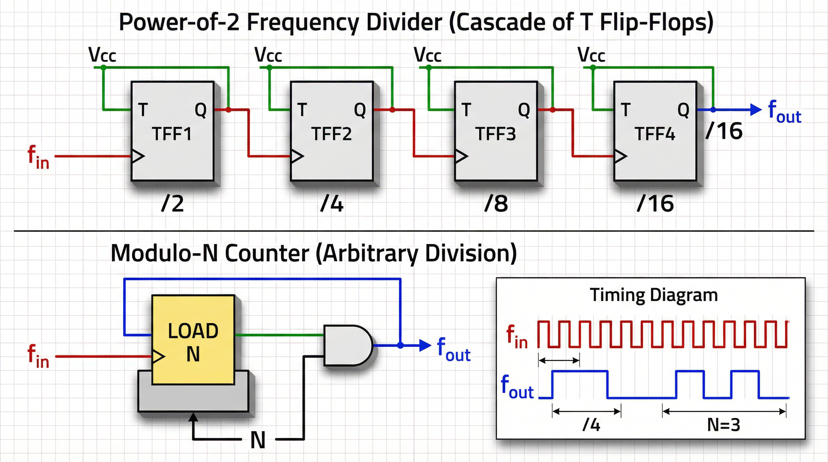
What if you need to divide by 4, 8, 16, or any power of 2? You could cascade T_FLIP_FLOPs—the output of the first becomes the clock for the second, and so on. This creates what’s known as an asynchronous or “ripple” counter. The first flip-flop divides by 2, the second divides the result by 2 (for a total of 4), the third divides by 8, and so on. For a division of , you need flip-flops.
However, a much more elegant and robust solution is to use a dedicated COUNTER component.
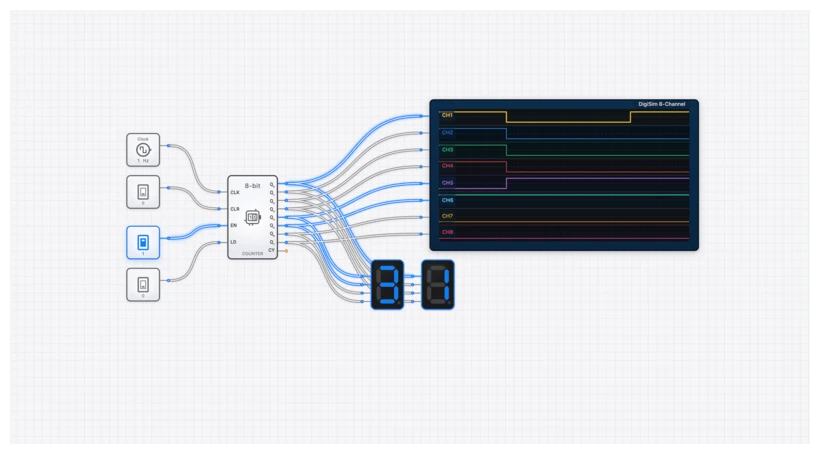
A binary COUNTER is, by its very nature, a frequency divider. Consider an 8-bit counter like the COUNTER_8BIT. Its outputs are Q0, Q1, Q2, …, Q7.
- Q0 toggles on every clock pulse, making it a divide-by-2 output.
- Q1 toggles every time Q0 goes from 1 to 0, making it a divide-by-4 output.
- Q2 toggles every time Q1 goes from 1 to 0, making it a divide-by-8 output.
- …and so on, up to Q7, which is a divide-by-256 output ().
This is an incredibly efficient way to get multiple divided clock frequencies from a single component.
The Real Challenge: Arbitrary Division (Modulo-N)
Dividing by powers of two is straightforward. But what if you need to divide by 10 for a decade counter, or by 60 for a seconds-to-minutes counter? This requires a modulo-N counter, which counts from 0 to N-1 and then resets.
The strategy is “count and reset.” You use a COUNTER and a COMPARATOR to detect when the count reaches a specific value, and then use that signal to trigger the counter’s reset input.
Let’s design a divide-by-10 (or MOD-10) counter:
- We need to count from 0 to 9. The counter should reset when it tries to go to 10.
- Use a
COUNTER_8BITand feed it aCLOCKsignal. - Use a
COMPARATOR_8BITto compare the counter’s output with the number 10 (binary00001010). - When the counter’s output equals 10, the
COMPARATOR’s “A=B” output will go HIGH. - Connect this “A=B” signal directly to the
COUNTER_8BIT’s synchronous reset (RST) input.
The result? The counter will count 0, 1, 2… up to 9. On the next clock pulse, it will momentarily become 10. The COMPARATOR immediately detects this, asserts the reset line, and the counter snaps back to 0 on the same clock edge. The state ‘10’ exists for only a few nanoseconds (the propagation delay of the logic) and is effectively skipped. The counter’s cycle length is 10 states (0 through 9), so any of its output bits will now operate on a cycle divided by 10.
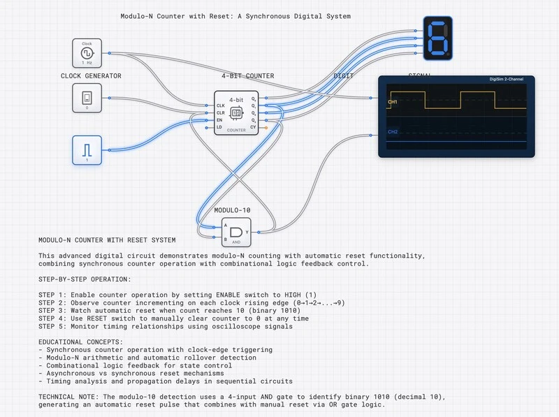
This “count-and-reset” technique is universal. To divide by any integer N, you simply set the COMPARATOR to detect N and reset the counter. I’ve built a template circuit that demonstrates this exact principle. You can change the CONSTANT value connected to the COMPARATOR to create a divider for any N you want.
Common Pitfalls and Pro-Tips
I’ve seen countless students get tripped up by a few common issues when designing dividers.
- Asynchronous Ripple Delay: If you build a divider by cascading individual flip-flops (a ripple counter), the delay adds up. The clock for the second flip-flop is delayed by the first, the third is delayed by the first two, and so on. For large division ratios, this “ripple delay” can become significant, causing timing errors and glitches. This is why using a synchronous component like the
COUNTERin digisim.io, where all flip-flops share the same clock, is nearly always the better, more reliable choice. - The 50% Duty Cycle Problem: A standard modulo-N divider does not produce a 50% duty cycle output for odd N. For example, a divide-by-3 counter might be HIGH for one clock cycle and LOW for two. For many applications this is fine, but if you need a symmetrical square wave, you need a more advanced design. The common solution involves using both the rising and falling edges of the clock to trigger two separate counters, whose outputs are then combined. It’s a clever trick worth exploring once you’ve mastered the basics.
Verification with the Oscilloscope
How do you know your divider is working correctly? You don’t guess, you measure. The OSCILLOSCOPE is your best friend for verifying timing relationships.
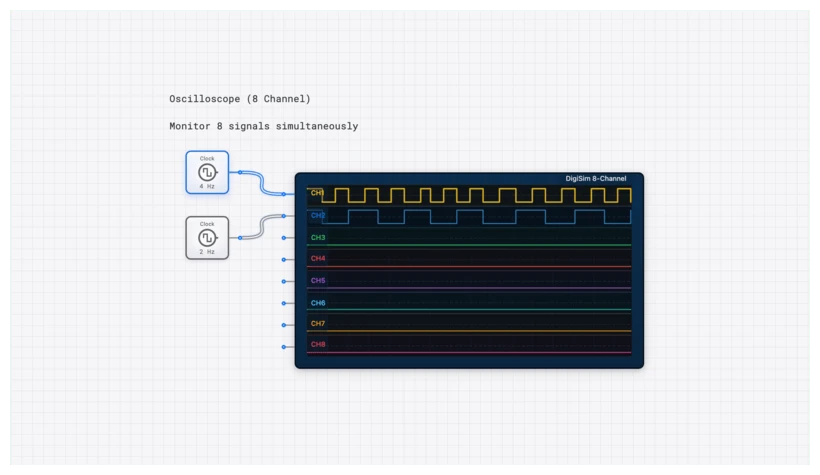
In digisim.io, use the OSCILLOSCOPE_8CH to debug your divider circuits:
- Channel 1: Connect your main input
CLOCK. This is your reference. - Channel 2: Connect the Q0 output of your
COUNTER. You should see a waveform with exactly half the frequency of the clock. - Channel 3: Connect the Q1 output. This waveform should have half the frequency of Q0 (one-quarter of the main clock).
- Channel 4: Connect the output of your reset logic (e.g., the
COMPARATORoutput in a MOD-N design). You should see a very brief pulse every N cycles.
Visualizing these signals side-by-side is the fastest way to confirm your division ratio and spot any unexpected behavior. A visual representation of timing is often more illuminating than any truth table. For complex interactions, our SimCast animation feature can step you through the signal propagation one gate at a time.
Real-World Applications: Where Dividers Live
Frequency dividers are everywhere, often hidden inside larger chips.
- The Digital Watch (RTC): The heart of most real-time clocks (RTCs) is a 32.768 kHz quartz crystal. Why this oddly specific number? Because . This allows a simple 15-stage binary counter (a chain of 15 divide-by-2 flip-flops) to divide this frequency down to exactly 1 Hz. This 1 Hz signal is what drives the “seconds” counter in your watch, phone, or computer.
- Baud Rate Generation: Serial communication protocols like UART (used in Arduino and many microcontrollers) require a specific clock rate, or “baud rate,” to function. A dedicated baud rate generator inside the chip uses a frequency divider to derive this precise rate (e.g., 9600 Hz) from the main system clock (e.g., 16 MHz).
- CPU and System Clocks: A modern CPU might have a core running at 5 GHz, but the memory bus runs at a lower frequency, and the PCIe bus at another. All these clocks are generated by a central clock management unit that uses a sophisticated network of frequency dividers and synthesizers (PLLs) to create the various clock domains needed by the system.