ANSI vs IEC Logic Symbols: A Schematic Reading Guide
ANSI uses distinctive shapes per gate; IEC uses uniform rectangles with '&' or '≥1' qualifiers. Both encode the same Boolean logic — read either fluently.

TL;DR: ANSI/MIL-STD-806 gives each logic gate a distinctive shape (D for AND, shield for OR). IEC 60617 places every gate in a uniform rectangle and identifies the function with a qualifying symbol inside (
&for AND,≥1for OR,=1for XOR). Both encode identical Boolean logic, and a circuit drawn in either standard simulates the same way.
A schematic from a European automation firm is mostly identical rectangles — one labeled &, another $\ge 1$, another =1. To a reader trained on American textbooks, these are unfamiliar, even though they represent the same AND, OR, and XOR gates as the distinctive D-shapes and shields.
This is the central divide in digital logic notation: the pictorial, distinctive shapes of the American National Standards Institute (ANSI) standard versus the systematic, rectangular symbols of the International Electrotechnical Commission (IEC) standard. In a globalized engineering environment, fluency in both is a professional requirement.
Two Philosophies, One Logic
At their core, both standards describe the same fundamental Boolean operations. Their differences lie in the philosophy of their visual representation.
1. ANSI/MIL-STD (The “Distinctive Shape” Standard)
Originating from US military standards (MIL-STD-806) in the 1960s, the ANSI system gives each logic gate a unique, memorable shape. The function is recognizable at a glance without reading any label. This works well for simple gate-level schematics and remains dominant in American education and industry.
2. IEC/IEEE (The “Rectangular” Standard)
The IEC 60617 standard (also adopted as IEEE Std 91) houses all logic functions in a uniform rectangular block. The specific function is identified by a “qualifying symbol” printed inside the block (e.g., ”&” for AND, "" for OR). This approach is less immediately intuitive for basic gates, but it scales cleanly to complex components like flip-flops, registers, and microcontrollers, where inventing a unique shape for every function would be impractical. It is the prevailing standard in Europe and most international documentation.
A Head-to-Head Comparison
Let’s break down the primary gates to see these two philosophies in action. We’ll start with the building blocks of all digital logic.
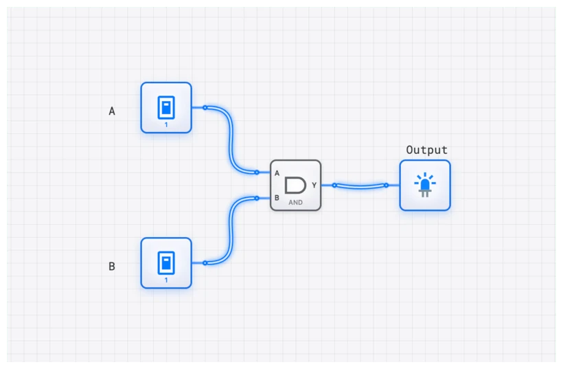
The AND Gate
The AND gate produces a high output (1) only when all of its inputs are high.
- Boolean Logic:
- ANSI Symbol: A distinctive “D” shape. The inputs enter the flat side, and the output leaves from the curved side. Its shape is a mnemonic for the “D” in “AND.”
- IEC Symbol: A rectangle containing an ampersand (&), the universal symbol for “and.” This qualifier tells you the logical AND function is being performed.
| Input A | Input B | Output Y |
|---|---|---|
| 0 | 0 | 0 |
| 0 | 1 | 0 |
| 1 | 0 | 0 |
| 1 | 1 | 1 |
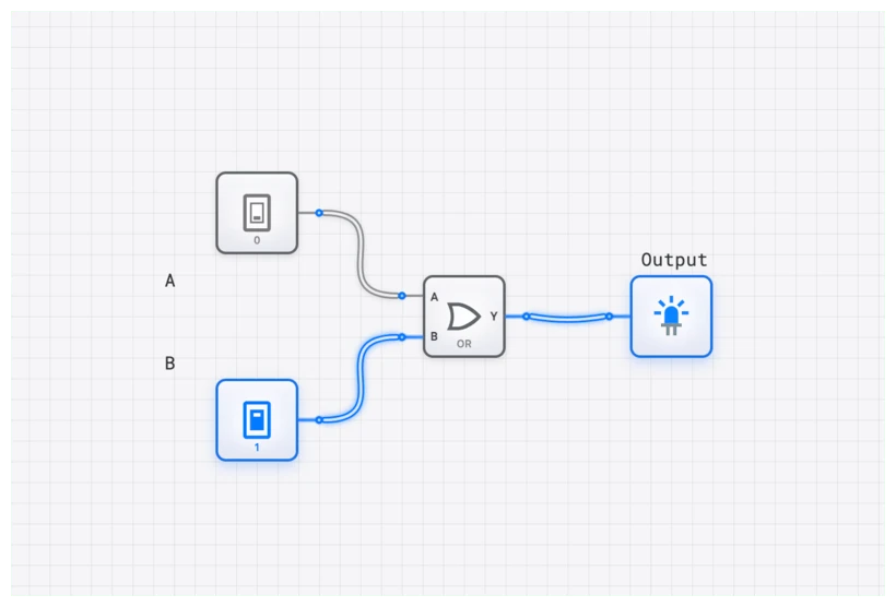
The OR Gate
The OR gate produces a high output (1) if any of its inputs are high.
- Boolean Logic:
- ANSI Symbol: A curved, shield-like shape with a pointed tip where the output emerges. The concave curve on the input side distinguishes it from the AND gate’s flat back.
- IEC Symbol: A rectangle with the qualifier . This is a beautifully logical description: the output is true if the number of true inputs is “greater than or equal to one.”
The NOT Gate (Inverter)
The simplest gate, the NOT gate, has a single input and a single output that is the logical opposite of the input.
- Boolean Logic:
- ANSI Symbol: A triangle pointing in the direction of signal flow, followed by a small circle or “bubble.” The triangle itself represents a BUFFER (passing the signal unchanged), and the bubble signifies inversion.
- IEC Symbol: A rectangle with a 1 inside, also followed by an inversion bubble. The 1 denotes a buffer.
The Universal Inversion Bubble
Both standards share one critical symbol: the small circle (bubble) that signifies logical negation. Whether placed at the output of an AND gate (making it a NAND) or at an input of an OR gate, the bubble always means “invert this signal.”
This is also the primary indicator of active-low logic, where a signal’s active state is 0 rather than 1. Active-low signals are conventionally written with an overbar () or a trailing “n” (RESETn). Missing a single bubble on a chip’s RESET or Enable pin is one of the most common schematic-reading errors and can lead to circuits that behave exactly opposite to the designer’s intent.
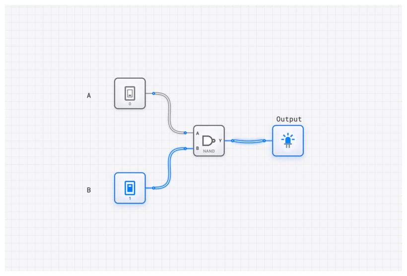
The Universal Gates: NAND and NOR
- NAND Gate: An AND gate followed by an inverter.
- Logic:
- ANSI: The “D” shape with an inversion bubble on the output.
- IEC: The & rectangle with an inversion bubble on the output.
- NOR Gate: An OR gate followed by an inverter.
- Logic:
- ANSI: The curved “shield” shape with an inversion bubble.
- IEC: The rectangle with an inversion bubble.
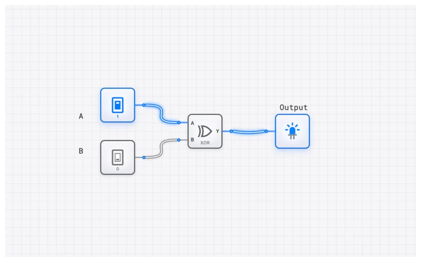
XOR and XNOR: The Logic of Difference
The Exclusive-OR (XOR) gate produces a high output only when its inputs are different. This is the heart of arithmetic circuits like the HALF_ADDER.
- XOR Logic:
- ANSI Symbol: The OR “shield” shape with an extra curved line on the input side. This extra line signifies the “exclusivity.”
- IEC Symbol: A rectangle with the qualifier . For a 2-input XOR this corresponds to “exactly one input is true.” (Caution: on a wide IEC
=1gate, the qualifier still denotes odd parity — the XOR of all inputs — not a literal one-hot detector. Three inputs all HIGH gives , even though three is not “exactly one.”) - XNOR Gate (Equivalence): The inverse of XOR, producing a high output when inputs are the same.
- Logic:
- Symbols: Both ANSI and IEC simply add an inversion bubble to their respective XOR symbols.
Beyond Gates: Sequential Logic and Dependency Notation
ANSI’s distinctive shapes work well for basic gates, but they do not scale to complex sequential components. There is no natural “distinctive shape” for a 4-bit counter with synchronous reset and asynchronous load.
This is where the IEC standard excels. It uses Dependency Notation — a system of letter codes inside the rectangular block to describe the functional relationship between inputs:
- G (And): Denotes an AND relationship.
- C (Control): Usually denotes a clock input for components like D_FLIP_FLOP or JK_FLIP_FLOP.
- R (Reset) and S (Set): Direct control of the state.
In digisim.io, when you place a REGISTER_8BIT, you’ll notice it follows this rectangular convention. It’s cleaner, it’s labeled, and it tells you exactly what each pin does without requiring you to memorize a specific silhouette.
Oscilloscope Verification: Seeing the Logic
Regardless of the symbol used, the physics of the signal remains the same. When transitioning between standards, use the OSCILLOSCOPE or OSCILLOSCOPE_8CH in digisim.io to verify that a “rectangle with an &” behaves identically to a D-shape AND.
For complex systems, monitor the inputs and outputs of a gate simultaneously on the OSCILLOSCOPE_8CH. The propagation delay () appears the same regardless of which symbol drew it.
Simulating on digisim.io: Your Personal Translator
Reading about these differences is one thing; seeing them in action is another. This is where a powerful simulator becomes an indispensable learning tool. On digisim.io, you can build a circuit using the symbols you’re most comfortable with and then practice translating them mentally.
Try this exercise:
- Open a new circuit and drag an AND, an OR, and a NOT gate onto the canvas.
- Connect them to an INPUT_SWITCH and an OUTPUT_LIGHT.
- Look at the shapes. If you’re in the US, you’re likely seeing ANSI.
- Now, challenge yourself: replace those gates with their IEC equivalents by looking at the component labels.
The underlying logic, the wiring, and the simulation results remain identical. You are looking at the same machine, just described in a different language. This interactive translation builds an intuitive understanding that static diagrams can never match.
Real-World Use: The Global Engineer’s Dilemma
So, which standard should you use? The pragmatic answer is: the one your project requires.
1. Reading Datasheets
This is the most common place you’ll encounter this divide. A datasheet from a US-based company like Texas Instruments will almost certainly use ANSI’s distinctive shapes for basic gates. However, if you’re looking at a datasheet for a modern ARM-based microcontroller or a European manufacturer like STMicroelectronics, you’ll see the IEC rectangular blocks. Being unable to read both fluently is a professional handicap.
2. Hybrid Schematics
In modern practice, you will often see a mix of both. Many engineers prefer the quick recognizability of ANSI symbols for basic gates (AND, OR, NOT) but switch to the powerful IEC standard for more complex components. The IEC’s dependency notation is far superior for defining the behavior of a complex block like a COUNTER_8BIT or a RAM module in a compact space.
Common Mistakes: The “Floating” Trap
Regardless of the symbol standard, one mistake kills more circuits than any other: Floating Inputs.
In digisim.io, a floating input (one not connected to anything) can lead to unpredictable behavior. In a real CMOS circuit, a floating input can pick up electrical noise and oscillate, causing the gate to overheat. Whether you are drawing an ANSI “D” or an IEC rectangle, always ensure your inputs are tied to a CONSTANT, a CONSTANT_ZERO, or an INPUT_SWITCH.
Related Topics in the Curriculum
As you continue exploring digital logic on digisim.io, these related topics will deepen your understanding:
- Digital Logic 101: AND, OR, NOT (the ANSI perspective)
- Mastering Boolean Algebra and De Morgan’s Laws (the math behind the symbols)
- Decoders and Encoders (where rectangular notation becomes essential)
- Visualizing the Fetch-Decode-Execute Cycle (the ultimate application of systematic symbols)
Summary: Two Standards, One Logic
The ANSI vs. IEC distinction is not about which standard is “better.” They are two mature systems optimized for different goals: ANSI for speed of recognition in simple gate-level schematics, IEC for systematic scalability in complex system-level designs.
| Aspect | ANSI (Distinctive Shape) | IEC (Rectangular) |
|---|---|---|
| Visual approach | Unique shape per function | Uniform rectangle + qualifier |
| Strength | Instant recognition of basic gates | Scales to complex components |
| Weakness | No natural shape for complex ICs | Requires reading the qualifier |
| Dominant region | North America | Europe, international standards |
| Negation indicator | Bubble (shared) | Bubble (shared) |
The goal is to become fluent in both: to look at an ANSI D-shape and an IEC rectangle with ”&” and immediately see the same logical conjunction. This bilingual fluency prevents schematic-reading errors and enables effective collaboration with international teams.
Ready to build your fluency? Continue with Digital Logic 101 to put each symbol to use, or open the AND gate component reference to compare its rendering in both standards.