Counters and State Machines: Controlling Digital Sequences
Counters cycle through binary sequences each clock pulse; FSMs extend that with conditional transitions. Build both and derive a traffic-light FSM.

TL;DR: A counter is a sequential circuit that steps through a fixed binary sequence on each clock edge. A finite state machine (FSM) generalizes this with conditional transitions driven by external inputs. Both are built from flip-flops plus combinational next-state logic — the foundation of every traffic-light controller, vending machine, and CPU control unit.
Digital systems do not just react to inputs; they remember where they have been and decide what to do next based on that history. This capability, sequential behavior, is what separates a combinational circuit (which forgets everything the instant its inputs change) from the intelligent controllers that run traffic lights, vending machines, and CPUs.
Two fundamental building blocks enable sequential behavior: counters, which step through a fixed numeric sequence, and finite state machines (FSMs), which can follow arbitrary sequences of states with conditional transitions. In this guide, we will build both from first principles, derive the logic for a traffic light controller, and explore the design methodology that scales from simple counters to complex CPU control units.
What is a Counter?
A counter is a sequential circuit that cycles through a predefined sequence of binary states on each clock pulse. Every counter is characterized by three properties:
- Modulus: The number of distinct states before the sequence repeats. A mod-8 counter has 8 states (0 through 7).
- Direction: Up-counters increment, down-counters decrement, and bidirectional counters can do either based on a control signal.
- Clocking: Synchronous counters have all flip-flops driven by the same clock edge; asynchronous (ripple) counters cascade each flip-flop’s output as the clock for the next.
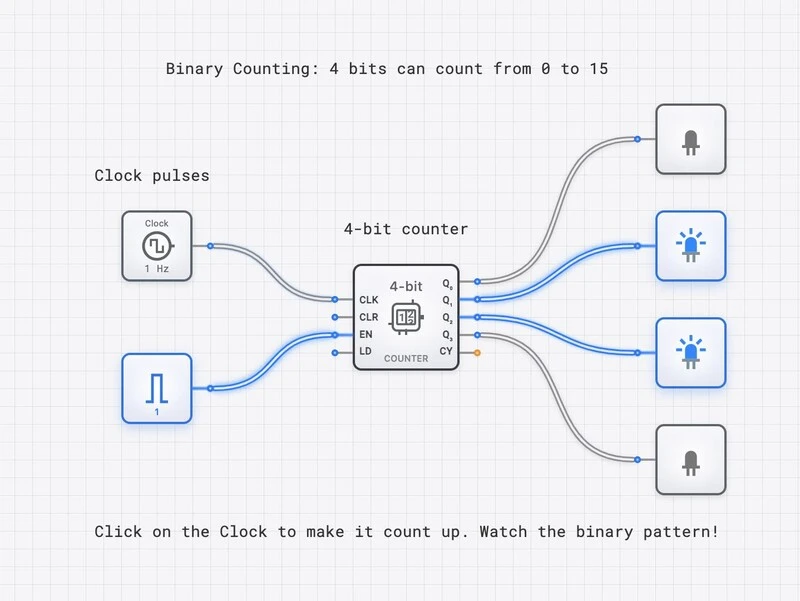
A 4-bit binary counter: on each clock pulse, it increments from 0000 to 1111, then wraps to 0000.
Building a 4-Bit Ripple Counter
The simplest counter is the ripple counter: chain T flip-flops (in toggle mode) so that each flip-flop’s output clocks the next stage.
| Clock Pulse | Decimal | ||||
|---|---|---|---|---|---|
| 0 | 0 | 0 | 0 | 0 | 0 |
| 1 | 0 | 0 | 0 | 1 | 1 |
| 2 | 0 | 0 | 1 | 0 | 2 |
| 3 | 0 | 0 | 1 | 1 | 3 |
| 4 | 0 | 1 | 0 | 0 | 4 |
| … | … | … | … | … | … |
| 15 | 1 | 1 | 1 | 1 | 15 |
| 16 | 0 | 0 | 0 | 0 | 0 (wrap) |
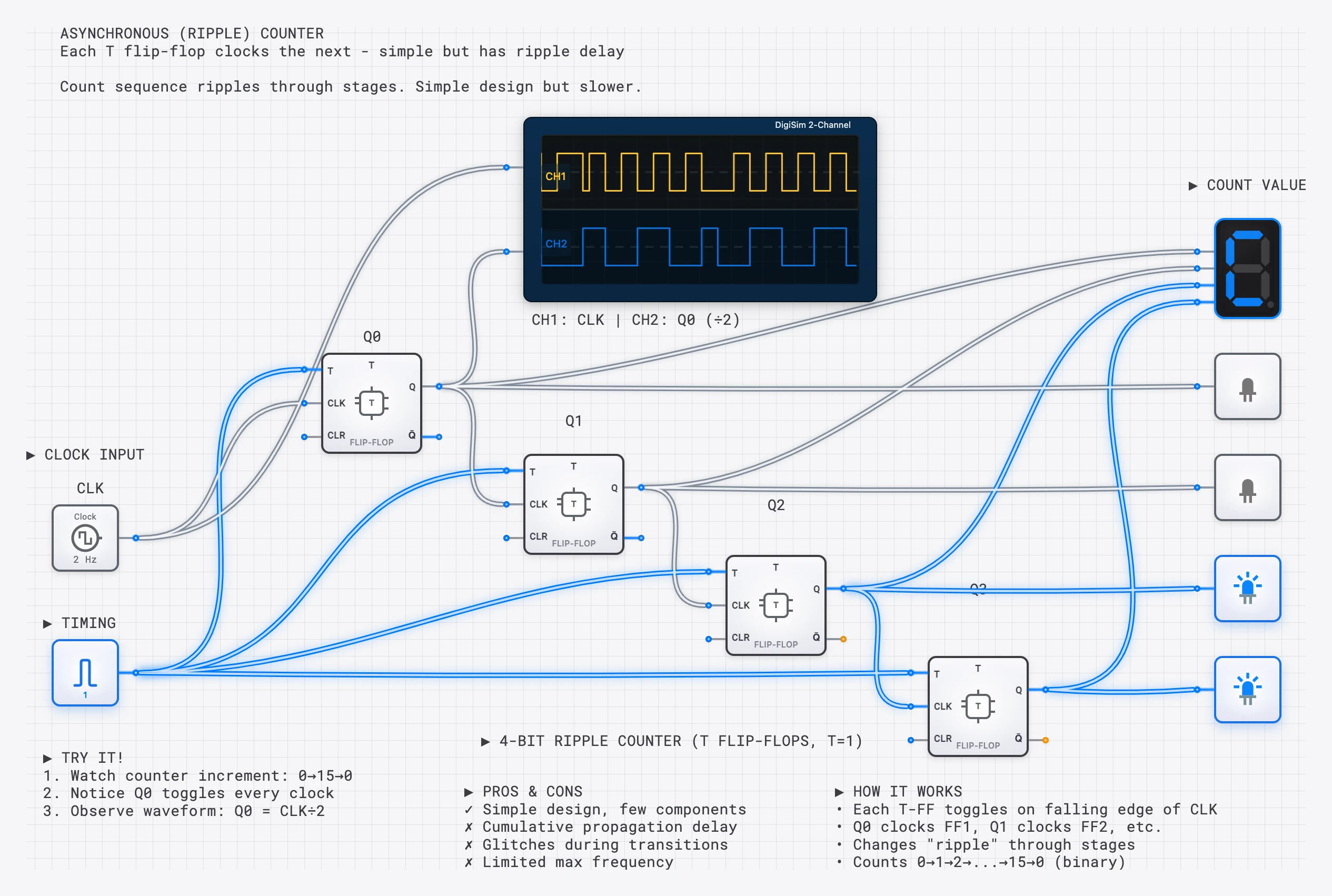
A ripple counter: toggles every clock, every other clock, every fourth, and so on.
Ripple Counter Limitations
In a ripple counter, each stage waits for the previous stage to toggle before it can respond. This creates an accumulating propagation delay. For an -bit ripple counter, the worst-case settling time is:
where is the propagation delay of a single flip-flop. This delay can cause glitches in downstream combinational logic that reads the counter outputs before they have fully settled. For high-speed or glitch-sensitive applications, synchronous counters (where all flip-flops share the same clock) are strongly preferred.
Synchronous Counters
A synchronous counter solves the ripple delay problem by clocking all flip-flops simultaneously from a single clock pulse. The trade-off is that we need additional combinational logic to determine which flip-flops should toggle on each clock edge.
For a 4-bit synchronous up-counter using T flip-flops, the toggle conditions are:
Each stage toggles only when all lower-order bits are 1 (meaning they are about to roll over from 1 to 0). This produces the correct binary counting sequence with all outputs changing simultaneously on the clock edge, eliminating glitch-prone intermediate states.
Modulo-N Counters
A modulo-N counter counts from 0 to and then resets to 0. It is built by adding reset logic to a standard binary counter. When the counter reaches the value , a comparator detects the match and resets the counter.
For a mod-6 counter (useful for dice displays or seconds-to-minutes conversion):
- Use a COUNTER_8BIT.
- Connect a COMPARATOR_8BIT to detect when the count equals 6 (binary 0110).
- Route the comparator’s “A=B” output to the counter’s RST input.
The counter cycles through states 0, 1, 2, 3, 4, 5 and then resets, producing a 6-state cycle.
What is a Finite State Machine?
A counter follows a fixed sequence. But what if the next state depends not only on the current state but also on external inputs? This is the domain of the Finite State Machine (FSM).
An FSM is a sequential circuit that can be in one of a finite number of states. On each clock edge, the machine transitions to a new state determined by the current state and the current inputs. The outputs can depend on the state alone (Moore machine) or on both the state and inputs (Mealy machine).
FSMs control:
- Traffic light sequences
- Vending machine logic
- Communication protocols (UART, SPI, I2C)
- CPU control units (fetch-decode-execute)
- Game logic and AI behavior
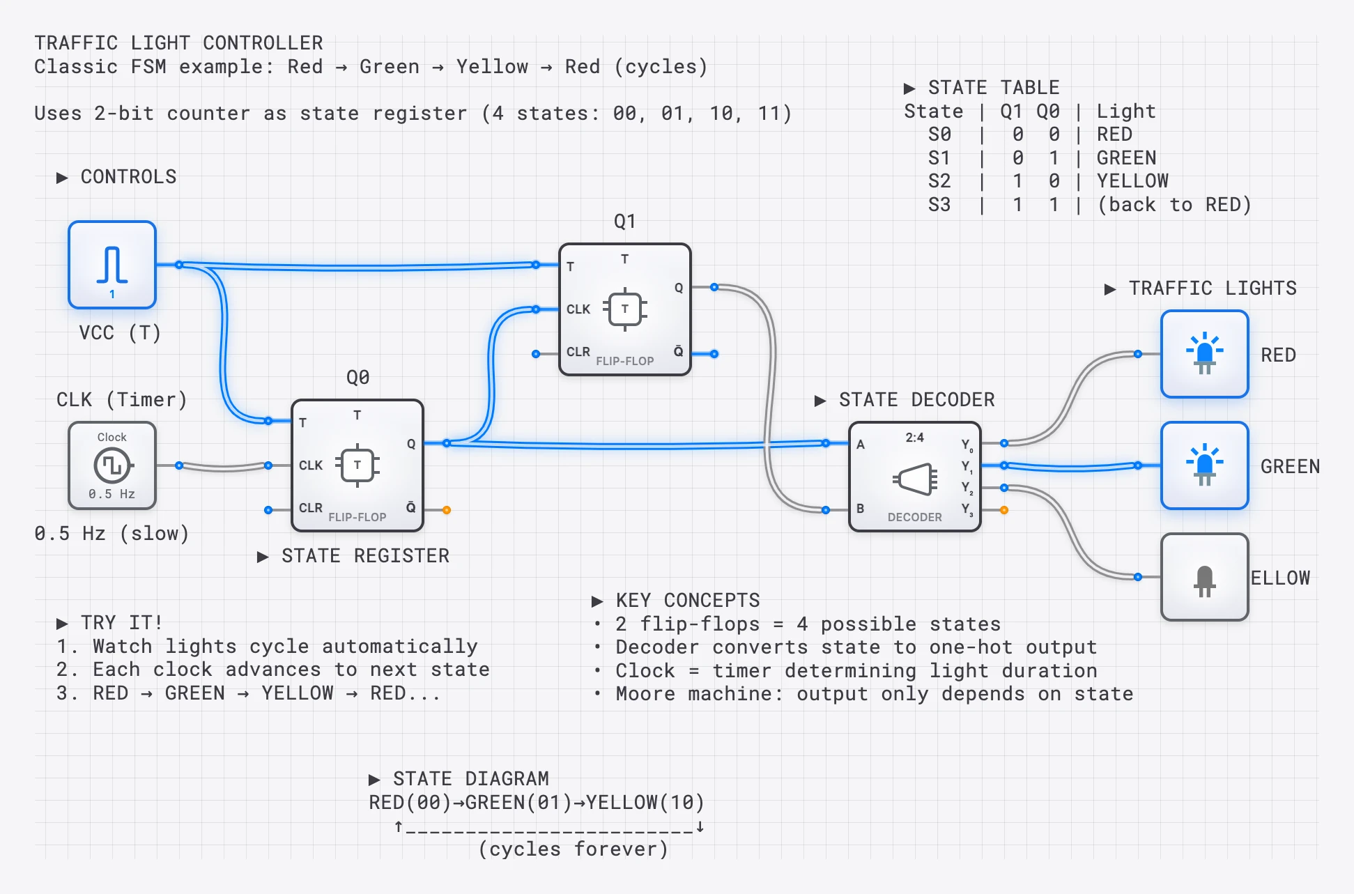
A traffic light FSM: states cycle through Green, Yellow, Red, controlled by timing logic.
FSM Architecture
Every FSM consists of three blocks:
- State Register: A set of flip-flops that store the current state as a binary code. For states, you need flip-flops.
- Next-State Logic: A combinational circuit that takes the current state and inputs and produces the next state. This is the “brain” of the FSM.
- Output Logic: A combinational circuit that generates the outputs based on the current state (and possibly the inputs).
Moore vs. Mealy Machines
The two canonical FSM types differ in how they generate outputs:
Moore Machine
Outputs depend only on the current state. The output is “attached” to the state, not to the transition. This means outputs change only on clock edges (when the state changes), making Moore machines inherently glitch-free on their outputs.
Example: Traffic Light Controller. Being in the “GREEN” state means the green light is on, regardless of any sensor inputs. The light changes only when the state changes.
| Current State | Green | Yellow | Red |
|---|---|---|---|
| S_GREEN | ON | off | off |
| S_YELLOW | off | ON | off |
| S_RED | off | off | ON |
Mealy Machine
Outputs depend on both the current state and the current inputs. This allows outputs to change mid-state in response to input changes, which can make Mealy machines faster to respond (by one clock cycle) but also susceptible to glitches on the outputs.
Example: Sequence Detector. A circuit that outputs HIGH only when it detects the bit pattern “101” in a serial input stream. The output depends on being in the “received 10” state AND the current input being “1.”
In practice, Moore machines are preferred for most hardware designs because their outputs are synchronous and predictable. Mealy machines are useful when you need the output to respond within the same clock cycle as the triggering input.
A 4-state finite state machine with state transitions controlled by input signals.
Case Study: Designing a Traffic Light Controller FSM
Let us design a complete traffic light controller for a simple intersection. This walkthrough demonstrates the full FSM design process from specification to circuit implementation.
Step 1: Define the States and Transitions
We need four states:
- S0 (Green NS): North-South green, East-West red. Duration: 30 seconds.
- S1 (Yellow NS): North-South yellow, East-West red. Duration: 5 seconds.
- S2 (Green EW): East-West green, North-South red. Duration: 30 seconds.
- S3 (Yellow EW): East-West yellow, North-South red. Duration: 5 seconds.
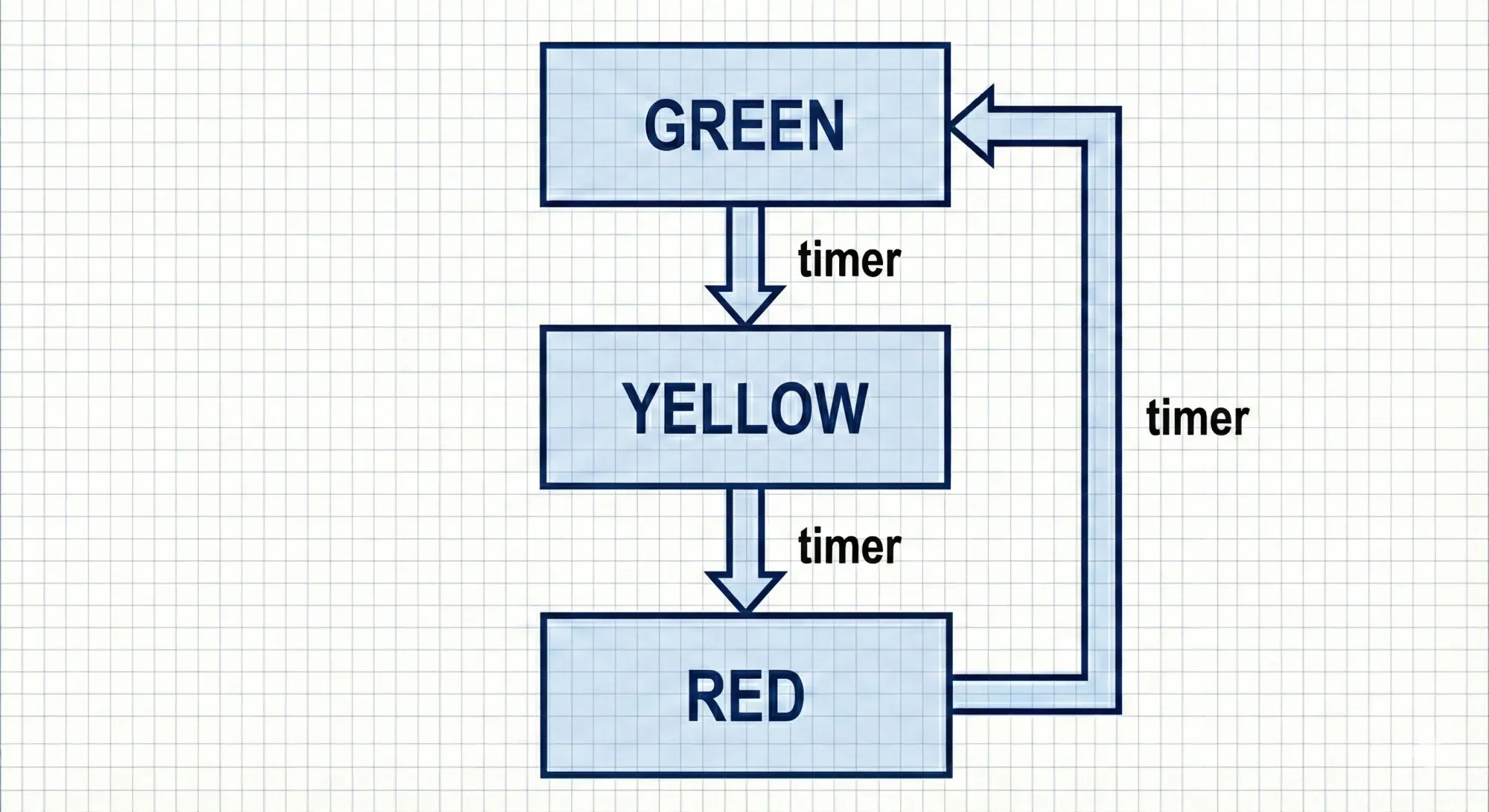
The state diagram forms a cycle: S0 -> S1 -> S2 -> S3 -> S0. Each transition occurs when a timer expires (input ). While the timer is counting (), the FSM stays in its current state.
Step 2: Assign Binary State Codes
With 4 states, we need 2 flip-flops (). We assign:
| State | ||
|---|---|---|
| S0 (Green NS) | 0 | 0 |
| S1 (Yellow NS) | 0 | 1 |
| S2 (Green EW) | 1 | 0 |
| S3 (Yellow EW) | 1 | 1 |
Step 3: Derive the State Transition Table
| Current State () | Timer () | Next State () |
|---|---|---|
| 00 (S0) | 0 | 00 (S0) |
| 00 (S0) | 1 | 01 (S1) |
| 01 (S1) | 0 | 01 (S1) |
| 01 (S1) | 1 | 10 (S2) |
| 10 (S2) | 0 | 10 (S2) |
| 10 (S2) | 1 | 11 (S3) |
| 11 (S3) | 0 | 11 (S3) |
| 11 (S3) | 1 | 00 (S0) |
Step 4: Derive Next-State Logic
Using D flip-flops (where ), we derive the next-state equations from the table above:
For (the next value of ):
This expression says: flips whenever and (i.e., transitioning out of S1 or S3).
For (the next value of ):
This says: flips whenever the timer expires, regardless of the current state. (When , stays the same; when , toggles.)
Step 5: Derive Output Logic (Moore)
Since this is a Moore machine, outputs depend only on the state:
| Output | Expression |
|---|---|
| Green NS | |
| Yellow NS | |
| Green EW | |
| Yellow EW | |
| Red NS | |
| Red EW |
Step 6: Build the Circuit on digisim.io
- State register: Place two D_FLIP_FLOP components for and .
- Next-state logic: Implement and using XOR and AND gates as derived above.
- Timer input: Use a CLOCK with appropriate frequency, or an INPUT_SWITCH for manual stepping.
- Output logic: Implement the six output expressions and connect them to OUTPUT_LIGHT components (colored if possible) representing the traffic signals.
- Verification: Step through the clock manually and verify the state transitions match the table.
More FSM Applications
Vending Machine Controller
A vending machine FSM tracks the total amount of money inserted. States represent cumulative totals (e.g., 0.25, 0.75, $1.00). Inputs are coin types (nickel, dime, quarter). Outputs are “dispense product” and “return change.” The state transition table for this FSM can have dozens of entries, but the design methodology is identical to the traffic light example.
Sequence Detector: Detailed Design
A sequence detector FSM monitors a serial input stream and asserts an output when a specific bit pattern is detected. Let us design a detector for the pattern “101” using the Mealy approach.
States:
- S0: Idle (no bits matched yet)
- S1: The last bit received was “1” (first bit of the pattern matched)
- S2: The last two bits were “10” (first two bits matched)
State transition table (Mealy, with overlapping detection):
| Current State | Input () | Next State | Output () |
|---|---|---|---|
| S0 | 0 | S0 | 0 |
| S0 | 1 | S1 | 0 |
| S1 | 0 | S2 | 0 |
| S1 | 1 | S1 | 0 |
| S2 | 0 | S0 | 0 |
| S2 | 1 | S1 | 1 |
Notice the last row: when in S2 (we have received “10”) and the input is 1, we have completed the pattern “101.” The output asserts immediately (Mealy behavior), and the next state is S1 because the final “1” could be the start of a new overlapping “101” pattern.
With 3 states, we need flip-flops. Assigning , , , the next-state equations for D flip-flops are:
This detector can be built with just a few AND, OR, and NOT gates, plus two D flip-flops.
CPU Control Unit
The most complex FSM in a computer is the control unit, which orchestrates the fetch-decode-execute cycle. Each phase of instruction processing is a state (or group of states), and the transitions depend on the current instruction’s opcode. A simple CPU might have 5-10 states; a pipelined processor’s control logic can have hundreds.
State Encoding Strategies
The choice of binary codes assigned to states significantly affects the complexity of the next-state and output logic. Three common strategies are:
Binary encoding assigns sequential binary values to states (00, 01, 10, 11). This minimizes the number of flip-flops ( for states) but can produce complex next-state logic with many gates.
One-hot encoding assigns one flip-flop per state. A 4-state machine uses 4 flip-flops, with exactly one flip-flop HIGH at any time (0001, 0010, 0100, 1000). This uses more flip-flops but dramatically simplifies the next-state and output logic, since each state is directly readable from a single flip-flop output. One-hot is the preferred encoding in FPGA designs, where flip-flops are abundant but complex combinational logic is expensive.
Gray code encoding assigns codes such that adjacent states differ by exactly one bit (00, 01, 11, 10). This minimizes the risk of glitches during state transitions, since only one flip-flop changes at a time. Gray encoding is useful in asynchronous interfaces and for states that drive outputs where glitches would be problematic.
For our traffic light controller with binary encoding, the next-state logic required two XOR gates and one AND gate. With one-hot encoding (using 4 flip-flops), the next-state logic for each flip-flop reduces to a single AND gate, but at the cost of two additional flip-flops.
From Counter to FSM: The Conceptual Bridge
A counter is actually a special case of an FSM. It has no external inputs influencing its transitions (or only a simple “enable” input), and its states follow a fixed numeric sequence. The moment you add conditional transitions based on external inputs, a counter becomes a general FSM.
Understanding this relationship is important because the design methodology is the same:
- Define the states and transitions (state diagram).
- Assign binary codes to states.
- Derive the state transition table.
- Extract the next-state and output logic equations.
- Build and verify the circuit.
Whether you are building a mod-10 counter or a UART protocol controller, these five steps will get you from specification to working hardware.
Common Pitfalls in FSM Design
Incomplete State Transitions
Every state must have a defined transition for every possible input combination. If you forget to specify what happens in a particular state when an unexpected input arrives, the synthesized logic may produce unpredictable behavior. When drawing state diagrams, always verify that each state has outgoing arrows for all input values.
Unreachable States
With flip-flops, you have possible states, but your FSM may use only a subset. For a 3-flip-flop design (8 possible states) with only 5 used states, the remaining 3 states are “unused.” If the FSM powers up in an unused state (due to random initialization), it may remain stuck there indefinitely.
The solution is to add default transitions from all unused states to a known valid state (typically the reset state). In the next-state logic, treat unused states as don’t-cares during Karnaugh map minimization, but verify that the resulting minimized logic naturally transitions out of them, or add explicit reset logic.
Output Glitches in Moore Machines
Even in Moore machines, brief glitches can appear on outputs during state transitions if multiple flip-flops change at slightly different times (due to clock skew or differing propagation delays). One-hot encoding eliminates this issue because only one flip-flop changes per transition. Alternatively, registering the outputs (passing them through an additional set of flip-flops) ensures they update cleanly on clock edges.
Verification with the Oscilloscope
When debugging counters and FSMs, the OSCILLOSCOPE_8CH is essential. Connect the clock to Channel 1 as your reference, and connect the state register outputs (, ) to Channels 2 and 3. Connect your FSM outputs (e.g., Green, Yellow, Red lights) to additional channels.
As you run the simulation, verify:
- State transitions occur only on clock edges.
- The outputs change correctly at each state transition.
- No glitches appear on outputs between transitions.
- The timer-to-transition timing is correct (e.g., 30 clock edges between S0 and S1).
For the sequence detector, connect the serial input to one channel and the detection output to another. You should see the output pulse exactly when the target pattern completes, and only then.
Try It Yourself
- Build a 3-bit up/down counter with a direction control input. When DIR=0, count up; when DIR=1, count down.
- Build a mod-6 counter that counts 0-5 and displays the result on a SEVEN_SEGMENT_DISPLAY.
- Design a traffic light FSM following the steps above. Use colored OUTPUT_LIGHT components and a slow CLOCK for the timer.
- Build a “101” sequence detector as a Mealy machine. Feed it a serial bit stream using an INPUT_SWITCH and verify that the output pulses only when the complete pattern is received.
- Challenge: Combine a mod-60 counter with a traffic light FSM, where the counter provides the timer signal. This creates a fully autonomous traffic light controller.
Continue with frequency division using flip-flops to slow a fast clock into the timer signal a real FSM needs, or open the D Flip-Flop reference — the storage element behind both counters and FSMs.