Product of Sums (POS): Boolean Form for Efficient Logic
Product of Sums (POS) is the dual of SOP, built from the 0s of a truth table. Derive maxterms, build OR-AND circuits, and contrast POS with SOP.

TL;DR: Product of Sums (POS) is the dual of Sum of Products: instead of ORing minterms for the 1s of a truth table, you AND maxterms for the 0s. POS produces fewer terms when a function has more 1s than 0s, mapping naturally to OR-AND or NOR-NOR hardware.
The Sum of Products (SOP) form is the natural starting point for most designers: you look at the 1s in a truth table, write minterms, and OR them together. But SOP is only half the story. Its algebraic dual, the Product of Sums (POS), approaches the same problem from the opposite direction — looking at the 0s instead of the 1s.
When a function’s truth table has more 1s than 0s, the POS form produces a shorter expression with fewer terms, leading directly to a circuit with fewer gates. Just as SOP maps to AND-OR (or NAND-NAND) logic, POS maps to OR-AND (or NOR-NOR) logic. Mastering both forms gives you the flexibility to choose the most efficient implementation for any given function.
Deconstructing the Product of Sums
At its core, a Product of Sums (POS) expression is exactly what the name implies: a logical product (AND) of one or more sum (OR) terms.
Consider the general form:
In this expression, each term within the parentheses—like —is a “sum term.” These individual sum terms are then “multiplied” (logically ANDed) together to produce the final output, .
This structure maps naturally to a two-level OR-AND circuit. The first level consists of OR gates that create the sum terms, and their outputs feed into a single AND gate for the final product.
The fundamental building block of a canonical POS expression is the maxterm. A maxterm is a sum term that contains every variable in the function, in either its true or complemented form. While a minterm (SOP) represents a single ‘1’ in a truth table, a maxterm represents a single ‘0’.
The Maxterm Convention: The Critical pitfall
This is where most learners trip up. When transitioning from SOP to POS, the convention for what each bit means in a truth table flips entirely.
In the SOP (minterm) convention:
- A ‘1’ means the variable is in its true form ().
- A ‘0’ means the variable is complemented ().
In the POS (maxterm) convention, it is the exact opposite:
- A ‘0’ means the variable is in its true form ().
- A ‘1’ means the variable is complemented ().
Why this inversion? It feels counter-intuitive until you realize the goal. A canonical POS expression is built from the rows where the function’s output is 0. The objective of each maxterm is to produce a ‘0’ for its specific input combination, and only that combination.
Let’s take a 3-variable maxterm, , which corresponds to the binary input (). For this maxterm to evaluate to , we need to construct a sum where every literal evaluates to for that specific input.
- For , we must use its complement, , which is .
- For , we must use its true form, , which is .
- For , we must use its complement, , which is .
The resulting maxterm is . When the input is , this evaluates to . For any other input combination, at least one of the literals will be , making the entire maxterm . This is the “Aha!” moment: the AND gate at the end of a POS circuit only outputs a if at least one of its OR-gate inputs drops to .
From Truth Table to POS Expression
The process of deriving a POS expression is systematic. Let’s look at a practical example. Suppose we have a logic function defined by the following truth table:
| A | B | C | Y | Maxterm |
|---|---|---|---|---|
| 0 | 0 | 0 | 1 | - |
| 0 | 0 | 1 | 0 | |
| 0 | 1 | 0 | 1 | - |
| 0 | 1 | 1 | 1 | - |
| 1 | 0 | 0 | 0 | |
| 1 | 0 | 1 | 1 | - |
| 1 | 1 | 0 | 0 | |
| 1 | 1 | 1 | 1 | - |
Step 1: Identify the Zeros
Scan the truth table and find all rows where the output is . In our table, these are rows 1, 4, and 6.
Step 2: Write the Maxterm for Each Zero
Apply the maxterm convention (0 = true, 1 = complement):
- Row 1 (001):
- Row 4 (100):
- Row 6 (110):
Step 3: AND the Maxterms
The final POS expression is the logical product:
This is often written in compact Pi () notation:
Notice the efficiency: the SOP expression for this same function would require five minterms (one for each ‘1’ in the truth table). By using POS, we only need three terms. In hardware, that translates to fewer gates (three 3-input OR gates + one 3-input AND gate, compared to five 3-input AND gates + one 5-input OR gate), less power consumption, and lower propagation delay ().
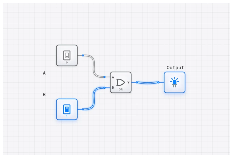
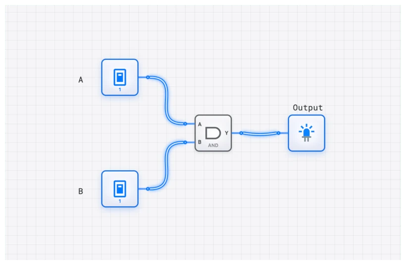
Implementing POS on digisim.io
The OR-AND structure of POS is straightforward to build on the digisim.io canvas. The same canonical form ideas appear in our Sum of Products guide and in Karnaugh map minimization.
The Build Guide
- Inputs: Place three INPUT_SWITCH components for , , and .
- Inversion: Use NOT gates to create the complements , , and .
- The OR Level: For our expression , drag three OR gates onto the canvas.
- Wire the first OR to , , and .
- Wire the second OR to , , and .
- Wire the third OR to , , and .
- The AND Level: Drag one 3-input AND gate onto the canvas.
- Final Connection: Connect the outputs of your three OR gates to the inputs of the AND gate. Attach an OUTPUT_LIGHT to the final AND output.
Verification with the Oscilloscope
To inspect the timing of a POS circuit, use the OSCILLOSCOPE_8CH. Connect the first three channels to your inputs () and the fourth channel to the final output .
As you toggle the switches, you’ll see the output stay HIGH most of the time. It will only “dip” to LOW when you hit the specific binary combinations 001, 100, or 110. This visual confirmation is vital for understanding how POS acts as a “filter” for specific forbidden states.
Common Pitfall: Floating Inputs and Propagation Delay
When building POS circuits, beginners often forget that an AND gate with a floating input might behave unpredictably. In digisim.io, ensure all inputs are tied to a CONSTANT or an INPUT_SWITCH.
Furthermore, consider the propagation delay (). In a POS circuit, the signal must pass through an OR gate and then an AND gate. If you are working on a high-speed design, like the ALU_8BIT explored in our advanced curriculum, these delays add up.
If your SOP version of the same circuit uses fewer levels (e.g., using a NAND-NAND implementation), it might actually be faster even if it uses more gates. This is the kind of trade-off professional engineers weigh every day.
Real-World Applications: Where POS Shines
Why bother with POS when SOP is “easier”? Because in the real world, we often define systems by their failures or exceptions.
1. Memory Address Decoding
In the classic Intel 8086 architecture, or even modern microcontrollers, address decoders are used to enable specific chips. Often, a chip should be active for almost the entire address range, except for a few specific “holes” reserved for I/O or system ROM.
Instead of writing a massive SOP expression for every valid address, designers use POS to define the “forbidden” addresses. If the address matches a forbidden range (a maxterm), the output drops to , disabling the chip. It’s cleaner, faster, and uses significantly less silicon.
2. Industrial Safety Interlocks
Imagine a high-pressure steam boiler. You want the system to remain active (Output=1) unless a dangerous condition occurs.
- Condition 1: Pressure > Threshold
- Condition 2: Temperature > Threshold
- Condition 3: Manual Emergency Stop Pressed
The logic is: “Keep running UNLESS (High Pressure) OR (High Temp) OR (E-Stop).” This is a single maxterm. The POS form allows you to add more “shutdown” conditions simply by adding more OR gates to the final AND gate. It is inherently more scalable for safety-critical logic.
The POS-to-NOR-NOR Connection
Just as SOP maps naturally to NAND-NAND logic, POS maps to NOR-NOR logic. The conversion uses De Morgan’s Laws and follows the same pattern.
Starting with our example:
Apply double negation:
Apply De Morgan’s to the outer bar (product becomes sum, each factor is complemented):
Each is a NOR operation (after accounting for the complemented inputs), and the outer expression is also a NOR. The result is a two-level NOR-NOR circuit.
In certain CMOS processes, NOR gates can be preferred over NAND gates for specific applications. The key insight: SOP pairs with NAND-NAND, POS pairs with NOR-NOR. Choosing the right canonical form at the start determines which universal gate you will use in the final implementation.
SOP vs. POS: When to Use Which
| Criterion | SOP (Sum of Products) | POS (Product of Sums) |
|---|---|---|
| Derived from | Rows where output = 1 | Rows where output = 0 |
| Building block | Minterms (AND terms) | Maxterms (OR terms) |
| Circuit structure | AND-OR (or NAND-NAND) | OR-AND (or NOR-NOR) |
| Fewer terms when | The truth table has few 1s | The truth table has few 0s |
| Design mindset | ”When should the output be ON?" | "When should the output be OFF?” |
For our example function with five 1s and three 0s, POS requires only 3 maxterms while SOP would require 5 minterms — a clear win for POS.
Conclusion
The Product of Sums teaches you to look at the zeros of a problem — the exceptions, the errors, the forbidden states. By mastering both POS and SOP, you gain the flexibility to choose the most efficient implementation for any function, whether that means fewer gates, lower propagation delay, or a better fit for your target technology.
Next in this series: simplify any function visually with Karnaugh maps, or open the OR Gate component reference and wire up the OR-AND circuit from this article.